Page 547 of 1216
FUEL SYSTEM - Fuel Tank
FUEL TANK cFWD>
,*. REMOVAL AND INSTALLATION
q?&g
NlMA-30-40 Nm
2-3 Nm22-29 ft.lbs.
---15-20 Nm
11-14 ft.lbs.
15-22 ft.lbs.Removal steps
l + 1. Return hosel +2. Vapor hose
3. Clamp
4. Fuel gauge unit connector
5. Electrical fuel pump connector
l + l q6. High pressure fuel hose
l + 7. Filler hose
l + 8. Vapor hose
~~ 9. Self-locking nut10. Tank band11. Fuel tank
l + 12. Vapor hosel + 13. Overfill limiter (Two-way valve)I)+ 14. Fuel gauge unitl + 15. Electrical fuel pump16. Drain plug
17. Fuel tank cap
18. Packing
19. Fuel filler neck$TEeverse the removal procedures to reinstall,(2) +e : Refer to “Service Points of Removal”:,,
(3) *+ : Refer to “Service Points of lnstallatlon .(4) m : Non-reusable parts
Page 548 of 1216
14-94FUEL SYSTEM - Fuel Tank
Outlet side_ Inlet side01
W838
Positioning projection
03A0220SERVICE POINTS OF REMOVALtilirro8AH
6. DISCONNECTION OF HIGH PRESSURE FUEL
H;OSECaution
Cover the hose connection with rags to prevent splash
of fuel that could be caused by some residual pressure
in the fuel pipe line.
INSPECTIONN14GCAll Check the hoses and the pipes for crack or damage.
l Check the fuel tank cap for malfunction.
l Check the fuel tank for deformation, corrosion or crack.
0,. Check the fuel tank for dust or foreign material.
NOTE
If the inside of the fuel tank is to be cleaned, use any one ofthe following:
(1) Kerosene
(2)
Trichloroethylene-(3) A neutral emulsion type detergent
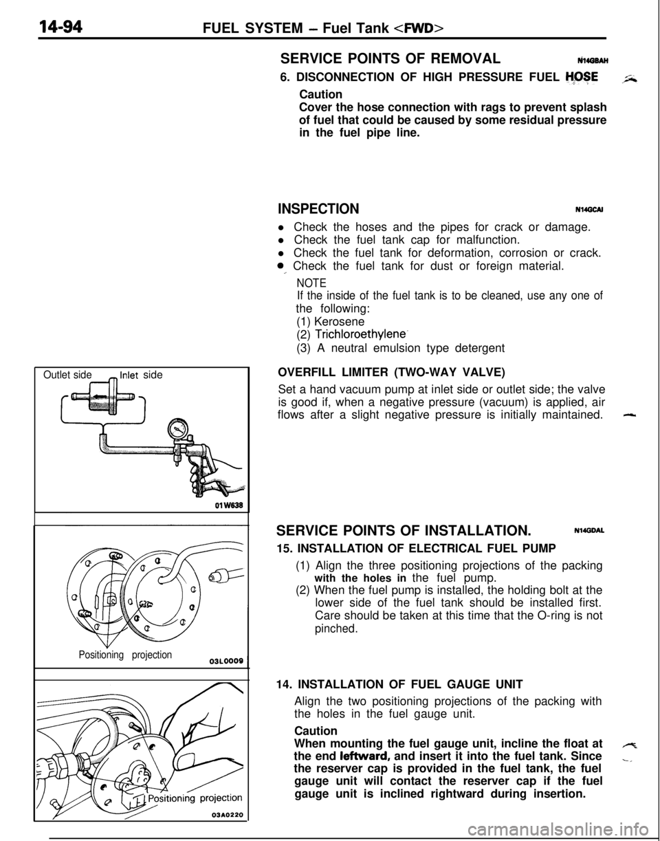
OVERFILL LIMITER (TWO-WAY VALVE)
Set a hand vacuum pump at inlet side or outlet side; the valve
is good if, when a negative pressure (vacuum) is applied, air
flows after a slight negative pressure is initially maintained.
SERVICE POINTS OF INSTALLATION.
Nl4DDAL15. INSTALLATION OF ELECTRICAL FUEL PUMP
(1) Align the three positioning projections of the packing
with the holes in the fuel pump.
(2) When the fuel pump is installed, the holding bolt at the
lower side of the fuel tank should be installed first.
Care should be taken at this time that the O-ring is not
pinched.14. INSTALLATION OF FUEL GAUGE UNIT
Align the two positioning projections of the packing with
the holes in the fuel gauge unit.
Caution
When mounting the fuel gauge unit, incline the float at
the end leftward, and insert it into the fuel tank. Since
the reserver cap is provided in the fuel tank, the fuel
gauge unit will contact the reserver cap if the fuel
gauge unit is inclined rightward during insertion.
-
4
-,
Page 550 of 1216
FUEL SYSTEM- Fuel Tank
Flare nut
Se&e side 03~043
03FOO76. CONNECTION OF HIGH PRESSURE FUEL HOSE TO
FUEL PUMP
Temporarily tighten the flare nut by hand, and then tighten
;Jtit to the specified torque, being careful that the high
’pressure fuel hose does not become twisted.
Caution
When tightening flare nut, be careful not to bend or
twist line to prevent damage to fuel pump low
connection.2. CONNECTION OF VAPOR HOSE/l. RETURN HOSE
When attaching the fuel hose to the pipe, be sure that the
hose is attached as shown in the illustration.
Standard value:
25-30 mm (1 .O-1.2 in.)
Page 551 of 1216
FUEL SYSTEM - Fuel Tank
FUEL TANK
i. REMOVAL AND INSTALLATION
N140A-A
_-Pre-removal Operation
eDraining of the fuel.@Release of Residual Pressure from High
Pressure Fuel Hose(Refer to
P.14-44.)Post-installation Operation
*Measurement of Fuel Pressure(Refer to P.14-44, 52.)l .Supplving of the Fuel.
1-2 Nm825-35 Nm
‘*-*: ft-‘bs*
9-14 Nm- 7-10 ft.lbs.-9
-7
03AO262
15-20 Nm
11-14 ftlbs.Removal steps
1. Fuel tankcap2. Packing
3. Drain plug4. Return hose
5. Vapor hose
4*6. High pressure fuel hose
7. Fuel filler hose
8. Cable band9. Protector
10. Vapor pipe11. Vapor hose
l 4 12. Hole cover13. Self-locking nut
14. Fuel tank
15. Overfill limiter (Two-way valve)
l + 16. Fuel pump and fuel gauge unit assembly
17. Fuel filler neck
FyTEeverse the removal procedures to reinstall.(2) ~~ : Refer to “Service Points of RemoveI”.(3) l + : Refer to “Service Points of Installation”.(4) m : Non-reusable parts
Page 552 of 1216
14-98FUEL SYSTEM -Fuel Tank 01
W636
Positioning projection03AO257
\03A0256SERVICE POINTS OF REMOVAL
N14G6AHl6. DISCONNECTION OF HIGH PRESSURE FUEL
HGSECaution
Cover the hose connection with rags to prevent splash
of fuel that could be caused by some residual pressure
in the fuel pipe line.
INSPECTIONN14GCAHl Check the hoses and the pipes for crack or damage.
l Check the fuel tank cap for malfunction.
l Check the fuel tank for deformation, corrosion or crack.
l Check the fuel tank for dust or foreign material.
NOTE
If the inside of the fuel tank is to be cleaned, use any one ofthe following:
(1) Kerosene
(2) Trichloroethylene
(3) A neutral emulsion type detergent
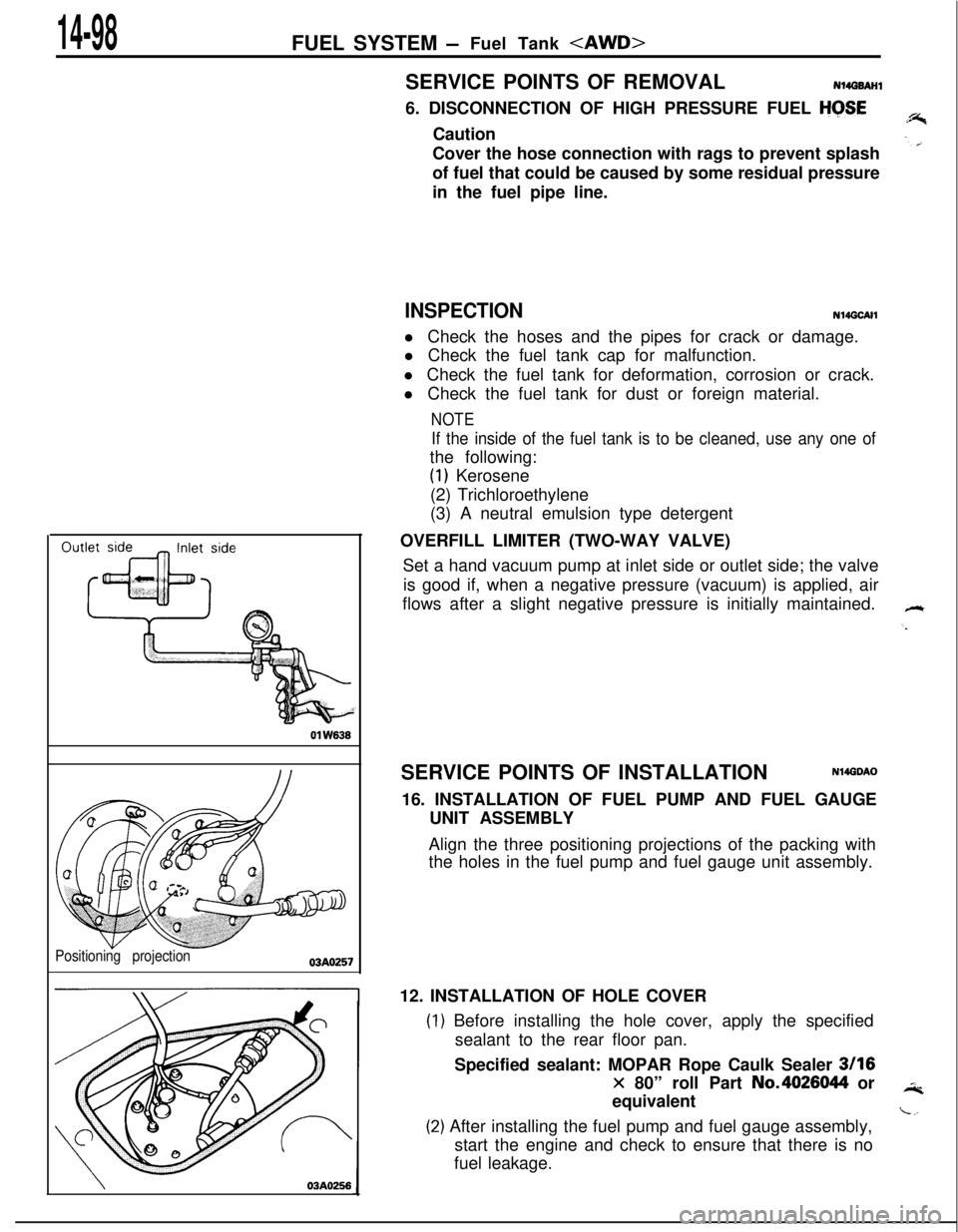
OVERFILL LIMITER (TWO-WAY VALVE)
Set a hand vacuum pump at inlet side or outlet side; the valve
is good if, when a negative pressure (vacuum) is applied, air
flows after a slight negative pressure is initially maintained.
SERVICE POINTS OF INSTALLATION
N14GDAO16. INSTALLATION OF FUEL PUMP AND FUEL GAUGE
UNIT ASSEMBLY
Align the three positioning projections of the packing with
the holes in the fuel pump and fuel gauge unit assembly.
12. INSTALLATION OF HOLE COVER
) Before installing the hole cover, apply the specified
sealant to the rear floor pan.
Specified sealant: MOPAR Rope Caulk Sealer
3116
x 80” roll Part No.4026044 or
equivalent
!) After installing the fuel pump and fuel gauge assembly,
start the engine and check to ensure that there is no
fuel leakage.
Page 553 of 1216
FUEL SYSTEM -Fuel Pump, Fuel Gauge Unit and Overfill Limiter (Two-Way Valve) p&&g
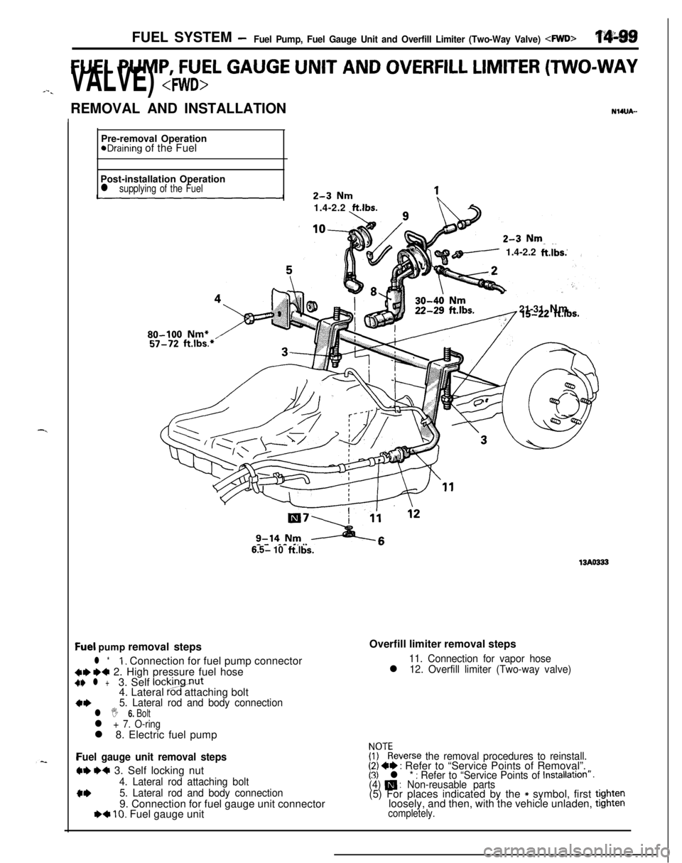
FUEL PUMP, FUEL GAUGE UNIT AND OVERFILL LIMITER (TWO-WAY
J-.VALVE) REMOVAL AND INSTALLATION
NWJA-Pre-removal Operation
eDraining of the Fuel
Post-installation Operation
l supplying of the Fuel1.4-2.2
ft.lbs.
/ 1.4-2.2ft.lbs.
21-31 Nm
80-100 Nm+
6.5- 10ftlbs.
13AO333
Qel pump removal steps
l *1. Connection for fuel pump connector
C+ ~~ 2. High pressure fuel hoseC+ l +3. Self lockingnut
4. Lateral Pod attaching bolt
a*5. Lateral rod and body connectionl I 6. Boltl + 7. O-ringl 8. Electric fuel pump
Fuel gauge unit removal steps
W e+ 3. Self locking nut
4. Lateral rod attaching bolt
c*5. Lateral rod and body connection9. Connection for fuel gauge unit connector
I)+ 10. Fuel gauge unitOverfill limiter removal steps
11. Connection for vapor hosel 12. Overfill limiter (Two-way valve)
FF:everse the removal procedures to reinstall.(2) +e : Refer to “Service Points of Removal”.(3) l * : Refer to “Service Points of Installation”.(4) m : Non-reusable parts(5) For places indicated by the * symbol, first tightenloosely, and then, with the vehicle unladen, tighten
completely.
Page 554 of 1216
14-100 FUEL SYSTEM- Fuel Pump, Fuel Gauge Unit and Overfill Limiter (Two-Way Valve) 4WD>SERVICE POINTS OF REMOVAL
NI4tmM2. DISCONNECTION OF HIGH PRESSURE FUEL HOSE
Refer to
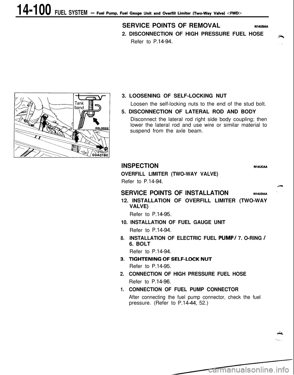
P.14-94.3. LOOSENING OF SELF-LOCKING NUT
Loosen the self-locking nuts to the end of the stud bolt.
5. DISCONNECTION OF LATERAL ROD AND BODY
Disconnect the lateral rod right side body coupling; then
lower the lateral rod and use wire or similar material to
suspend from the axle beam.
INSPECTION
OVERFILL LIMITER (TWO-WAY VALVE)Refer to
P.14-94.
N14UcM
SERVICE POINTS OF INSTALLATIONN14UDAA12. INSTALLATION OF OVERFILL LIMITER (TWO-WAY
VALVE)
Refer to
P.14-95.
10. INSTALLATION OF FUEL GAUGE UNITRefer to
P.14-94.
8.INSTALLATION OF ELECTRIC FUEL PUMP/ 7. O-RING /6. BOLT
Refer to
P.14-94.
3.TIGHTENING OF SELF-LOCK NUTRefer to
P.14-95.
2.CONNECTION OF HIGH PRESSURE FUEL HOSERefer to
P.14-96.
1.CONNECTION OF FUEL PUMP CONNECTOR
After connecting the fuel pump connector, check the fuelpressure. (Refer to P.1444, 52.)
Page 555 of 1216
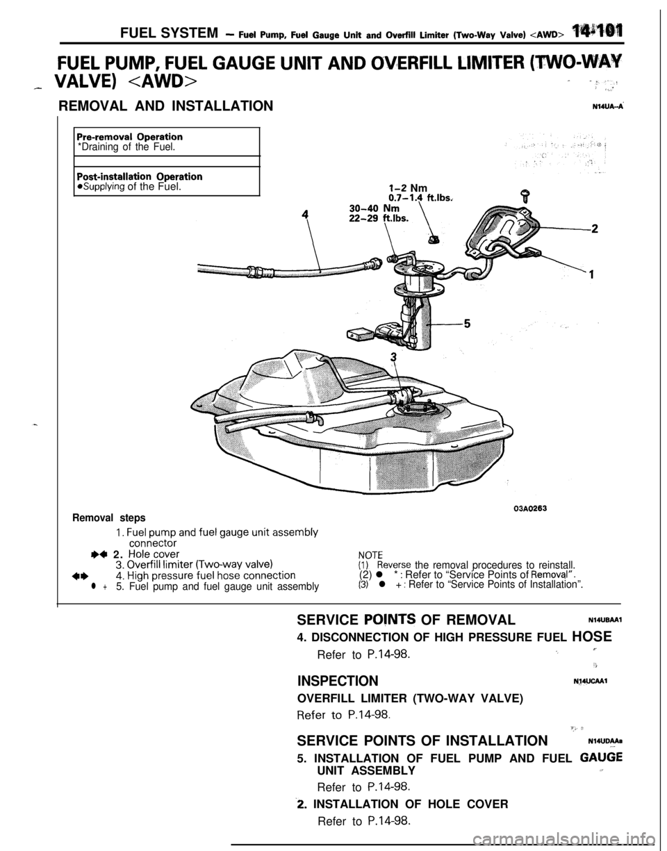
FUEL SYSTEM- Fuel Pump, Fuel Gauge Unit and Overfill Limiter (Two-Way Valve)
FUEL PUMP, FUEL GAUGE UNIT AND OVERFILL LIMITER (TWO-WAY
_ VALVE) - “:“-: _...REMOVAL AND INSTALLATION
N14UA-A’
Pre-removal Operation
*Draining of the Fuel.
Post-installation Operationasupplying of the Fuel.1-2 Nm0.7-1.4 ft.lbs.
Removal steps03A0263
1. Fuel pump and fuel gauge unit assemblyconnector
I)4 2. Hole cover3. Overfill limiter (Two-way valve)FyEeverse the removal procedures to reinstall.
4*4. High pressure fuel hose connection(2) l * : Refer to “Service Points of Removql”.
l +5. Fuel pump and fuel gauge unit assembly(3) l + : Refer to “Service Points of Installation”.SERVICE
POVNTS OF REMOVALN14UBAAI4. DISCONNECTION OF HIGH PRESSURE FUEL HOSE
Refer to
P.14-98.I’.,
3
INSPECTIONN~4UCAAlOVERFILL LIMITER (TWO-WAY VALVE)Refer
to P.14-98.“,, 2SERVICE POINTS OF INSTALLATION
N14UDAAa5. INSTALLATION OF FUEL PUMP AND FUEL
GAU6EUNIT ASSEMBLY1,Refer to
P.14-98.
-2. INSTALLATION OF HOLE COVER
Refer to
P.14-98.