1991 MITSUBISHI ECLIPSE fuel pressure
[x] Cancel search: fuel pressurePage 527 of 1216

FUEL SYSTEM - MPI System Inspection <2.0L DOHC Engine>
SELF-DIAGNOSIS14-73
N14PAAEThe engine control unit monitors the input/output signals
(some signals at all times and the others under specified
conditions) of the engine control unit.
When it is noticed that an irregularity has continued for a
specified time or longer from when the irregular signal is
initially monitored. Passing a certain number, the engine
control unit judges that an irregularity has occurred, memorizesthe malfunction code, and outputs the signal to the
self-diagnosis output terminal.
There are 14 diagnosis items, and the diagnosis results can beread out with a voltmeter.
Moreover, since memorization of the malfunction codes is
backed up directly by the battery, the diagnosis results are
memorized even if the ignition key is turned off. The malfunc-
tion codes will, however, be erased when the battery terminal
or the engine control unit connector is disconnected.
CautionIf the sensor connector is disconnected with the ignition
switch turned on, the malfunction code is memorized. In
this case, disconnect the battery terminal
(-) for 10seconds or more, and the diagnosis memory will be
erased.The 14 diagnosis items are provided as follows, and if plural
items are activated, they are all indicated sequentially from thesmallest code number.
arometnc pressure sensor
CHECK PROCEDURE (SELF-DIAGNOSIS)Precautions for OperationN14PCAE2(1) When battery voltage is low, no detection of failure is
possible. Be sure to check the battery for voltage and otherconditions before starting the test.
(2) Diagnosis item is erased if the battery or the engine controlunit connector is disconnected. Do not disconnect the
battery before the diagnosis result is completely read.
(3) After check and correction are over, disconnect ground
cable for 10 seconds or more from negative terminal of
battery and connect it again to make sure that failure code
is erased.
Page 528 of 1216

FUEL SYSTEM- MPI Svstem InsDection <2.0L DOHC Engine>
MPI
diagnosis
I Ground
INSPECTION PROCEDURE - USING VOLTMETERN14PCAGZ
(1) Connect an analogue voltmeter to the self-diagnosis con-
nector.(2) Turn ignition switch to ON, and indication of engine control
unit memory contents will immediately start. If the system
is in normal condition, pointer of voltmeter indicates normalpattern. If any abnormality is in memory, the pointer of
voltmeter will deflect, indicating abnormal item as de-
scribed in “Diagnosis Chart”.
After recording the abnormal item, check and repair each
part according to the check items in “Diagnosis Chart”.
(3) If the defective parts have been repaired, disconnect the
negative terminal of battery cable for
10 seconds or more
and connect it again to make sure that the abnormal code
has been erased.
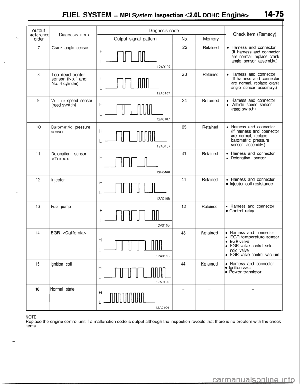
DIAGNOSIS CHART (FAULT TREE)NlQPRADoutputDiagnosis codeIreference
Dragnosrs Item- Check item (Remedy)
orderOutput signal patternNo.Memory
1Engine controlunit- - W$$ace engine control: I
12A0104
2Oxygen sensor11Retainedl Harness and connector:-J-l-J-0 Oxygen sensor
o Fuel pressure
0 Injectors(Replace if defective)
12A0104l Intake air leaks
3Air flow sensor
:-rLJL ‘*
Retainedl Harness and connector
(If harness and connector
are normal, replace airflow sensor assembly.)
12A0104
4Intake au
J--lNlL l3
Retarnedl Harness and connectortemperature sensor Hl Intake air temperature
sensor
12A0104
5Throttle postron
:n l4
Retainedl Harness and connector
sensorl Throttle position sensorl Idle position switch
17A0104
6Engine coolant
:nn 2’
Retainedl Harness and connectortemperature sensorl Engine coolant temper-
ature sensor
12A0107
Page 529 of 1216

FUEL SYSTEM - MPI Svstem InsDection <2.0L DOHC Engine>
outputDiagnosis codeIreferenceDragnosrs ItemCheck item (Remedy)orderOutput signal patternNo.Memory
7Crank angle sensor
:nn **
Retainedl Harness and connector
(If harness and connector
are normal, replace crank
angle sensor assembly.)
12A0107
8Top dead center
:- 23
Retainedl Harness and connectorsensor (No.1 and(If harness and connector
No. 4 cylinder)are normal, replace crank
angle sensor assembly.)
12A0107
9Vehicle speed sensor24Retainedl Harness and connector
(reed swatch)H
I u I nlvln
l Vehicle speed sensor
(reed switch)
L12A0107
10Barometnc pressure25Retainedl Harness and connector
sensorH(If harness and connector
are normal, replace
LULllnMllbarometric pressure
12A0107sensor assembly.)
11Detonation sensorRetainedl Harness and connector
:m 31
l Detonation sensor
12R0468
12Injector
:m 41
Retainedl Harness and connector0 Injector coil resistance
12A0105
13Fuel pump42Retainedl Harness and connectorH
UUUI nn
0 Control relay
L12A0105
14EGR
Hl EGR temperature sensor
u u u I nnn
l EGRvalvel EGR valve control sole-Lnoid valve
12A0105l EGR valve control vacuum
15Ignition coil44Retainedl Harness and connectorH
UUUL-llMlL
0 Ignition coil0 Power transistor
L12A0105
16Normal state---H
L
12A0104
NOTEReplace the engine control unit if a malfunction code is output although the inspection reveals that there is no problem with the check
items.
Page 533 of 1216

FUEL SYSTEM - MPI System Inspection <2.0L QOHC Engine>14-79EGR TEMPERATURE SENSOR
N14RCHAaRefer to GROUP 25
- Exhaust Gas Recirculation System.
VEHICLE SPEED SENSOR
Refer to GROUP 8
- Meters and Gauges.
N140EBBaAIR CONDITIONER SWITCH
Nl4QQAEaRefer to GROUP 8
- Column Switch.
POWER STEERING OIL PRESSURE SWITCH
N14RCJBRefer to GROUP 19 for power steering system inspection.
INJECTORS
NWXAHCHECKING OPERATION SOUND
Using a sound-scope, check the operation sound (“chi-chi-chi”)of the injectors during idling or during cranking.
Check to be sure that the operation sound increases when the
engine speed is increased.
Caution
Note that the sounds of other injectors may be heard even
though the injector being checked is not operating, so caremust be taken when checking.
NOTEIf the operation sounds cannot be heard, check the injector
activation circuit.
If this circuit is normal, there is probably a malfunction of the
injector or of the engine control unit.
MEASURING OF RESISTANCE BETWEEN TERMINALS
(1) Disconnect the connector for the injectors.
(2) Measure the resistance between terminals.
Standard value:
-16 S2 [at 20°C (68”F)]
- 3 52 [at 20% (68”F)]
(3) Connect the connector for the injectors.
IDLE SPEED CONTROL SERVO
N14QUADCHECKING OPERATING SOUND
(1) Check that when the ignition switch is placed in the ON
position (the engine not started), the operating sound of thestepper motor can be heard over the idle speed control
servo.
(2) If no operating sound can be heard, check the stepper
motor drive circuit.
(If the circuit is good, a defective stepper motor or engine
control unit is suspected.)
Page 536 of 1216

14-82FUEL SYSTEM - MPI System Inspection <2.0L DOHC Engine>
\ \\I \3FUO352
,\ \
\I \3FUO353
,\ ‘\R/
\ \\I \3FUo354
POWER TRANSISTORRefer to GROUP 8
- Ignition System
NlIAcQAl
a-4
AIR CONDITIONER POWER RELAYN14NCl.a -Refer to GROUP 24
- Air Conditioner.
PURGE CONTROL SOLENOID VALVEN14RCKARefer to GROUP 25
- Evaporative Emission Control System.
EGR CONTROL SOLENOID VALVE
N14NCURefer to GROUP 25
- Exhaust Gas Recirculation System.
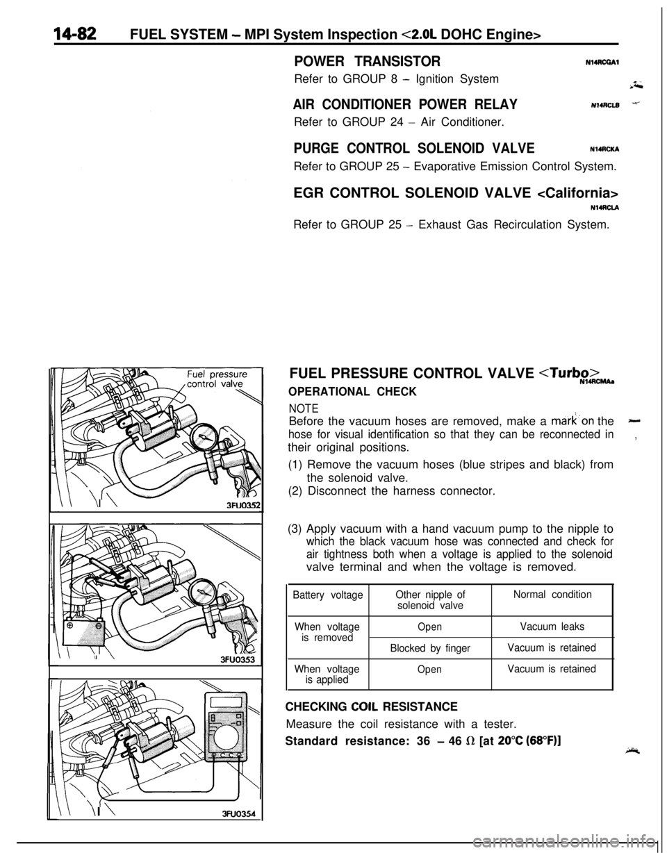
FUEL PRESSURE CONTROL VALVE
NOTEBefore the vacuum hoses are removed, make a mark’on the
-
hose for visual identification so that they can be reconnected in,their original positions.
(1) Remove the vacuum hoses (blue stripes and black) from
the solenoid valve.
(2) Disconnect the harness connector.
(3) Apply vacuum with a hand vacuum pump to the nipple to
which the black vacuum hose was connected and check for
air tightness both when a voltage is applied to the solenoidvalve terminal and when the voltage is removed.
Battery voltageOther nipple of
solenoid valveNormal condition
When voltage
is removed
When voltage
is applied
OpenVacuum leaks
Blocked by fingerVacuum is retained
OpenVacuum is retainedCHECKING
COIL RESISTANCE
Measure the coil resistance with a tester.
Standard resistance: 36
- 46 R [at 20°C (68”F)]
Page 537 of 1216

INJECTORFUEL SYSTEM
- Injector14-83
* ‘- REMOVAL AND INSTALLATIONNWSA-A
Post-installation Operation
l Measurement of Fuel Pressure(Refer to P.14-44. 52.)
4.8L Engine><2.0L DOHC
Engilme>11R7-11 Nm
-hl ft.lbs.-zF!
;533i5,b;m-. .-Y-71s4-6 Nma-3-4 ft.lbs.
03AOlSS::,
4*12:
Center cover
Connection for control harness
Delivery pipe
d-- -13. Insulator4-6 Nm
3-4
ft.lbs.
lo-13 Nm
7-9 ft.lbs.Removal steps
1. Connection for breather hose
2. Connection for PCV hose
+e *+3. Connection for high pressure fuel hose
4. O-ring
5. Connection for vacuum hose6. Connection for fuel return hose
l + 7. Fuel pressure regulator8. O-ring
9. Accelerator cable clamp
03AO19014. Insulator
** l + 15. InjectorH 16. O-ringl + 17. Grommet
!PTkeverse the rem&al procedures to reinstall.(2) +* : Refer to “Service Points of Removal”.
(3) l * : Refer to “Service Points of Installatron”(4) m : Non-reusable parts
Page 538 of 1216

14-84FUEL SYSTEM - Injector
03*0095
Delivery pipe03A0095-SERVICE POINTS OF REMOVAL
H4s0m1‘~
3.DISCONNECTION OF THE HIGH PRESSURE FlJFL HOSE /;;
Bleed the residual pressure within the fuel pipe line’& as to~prevent the flow of fuel.
For information concerning the method to be folfowed for
bleeding the residual pressure, refer to
P.14-44.Caution
Cover the hose connection with rags to prevent splash,
of fuel that could be caused by some residual pressure
in the fuel pipe line.
12. REMOVAL OF DELIVERY PIPE/ 15. INJECTOR
Remove the deliver-y pipe (with the injectors attached to it).Caution
Care must be taken, when removing the delivery pipe,
not to drop the injector.
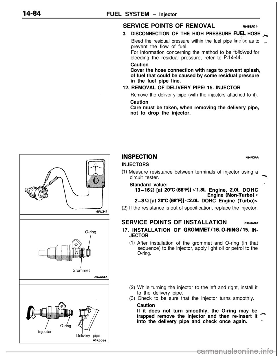
INSPEiZTION
INJECTORS
N14NGAA
(1) Measure resistance between terminals of injector using a
circuit tester.+-%Standard value:
/13-1652 [at
20°C (68”F)] <1.8L Engine, 2.0L DOHC
Engine
(NoniTurbo)>
2-3Q [at 20°C (68”F)] <2.0L DOHC Engine (Turbo)>
(2) If the resistance is out of specification, replace the injector.
SERVICE POINTS OF INSTALLATION
N14SDAEl’17. INSTALLATION OF
GROMMET/lG. 0-RINGI15. IN-
JECTOR
(I) After installation of the grommet and O-ring (in that
sequence) to the injector, apply light oil or petrol to the
O-ring.(2) While turning the injector to.the left and right, install it
to the delivery pipe.
(3) Check to be sure that the injector turns smoothly.
Caution
If it does not turn smoothly, the O-ring may be
~trapped remove the injector and then re-insert it
into the delivery pipe and check once again.
L
Page 539 of 1216

FUEL SYSTEM - Injector/Throttle Body <1.8L Engine>14-85
Delivery pipe
Fuel pres
regulator
O-ringY pipe
O-kg
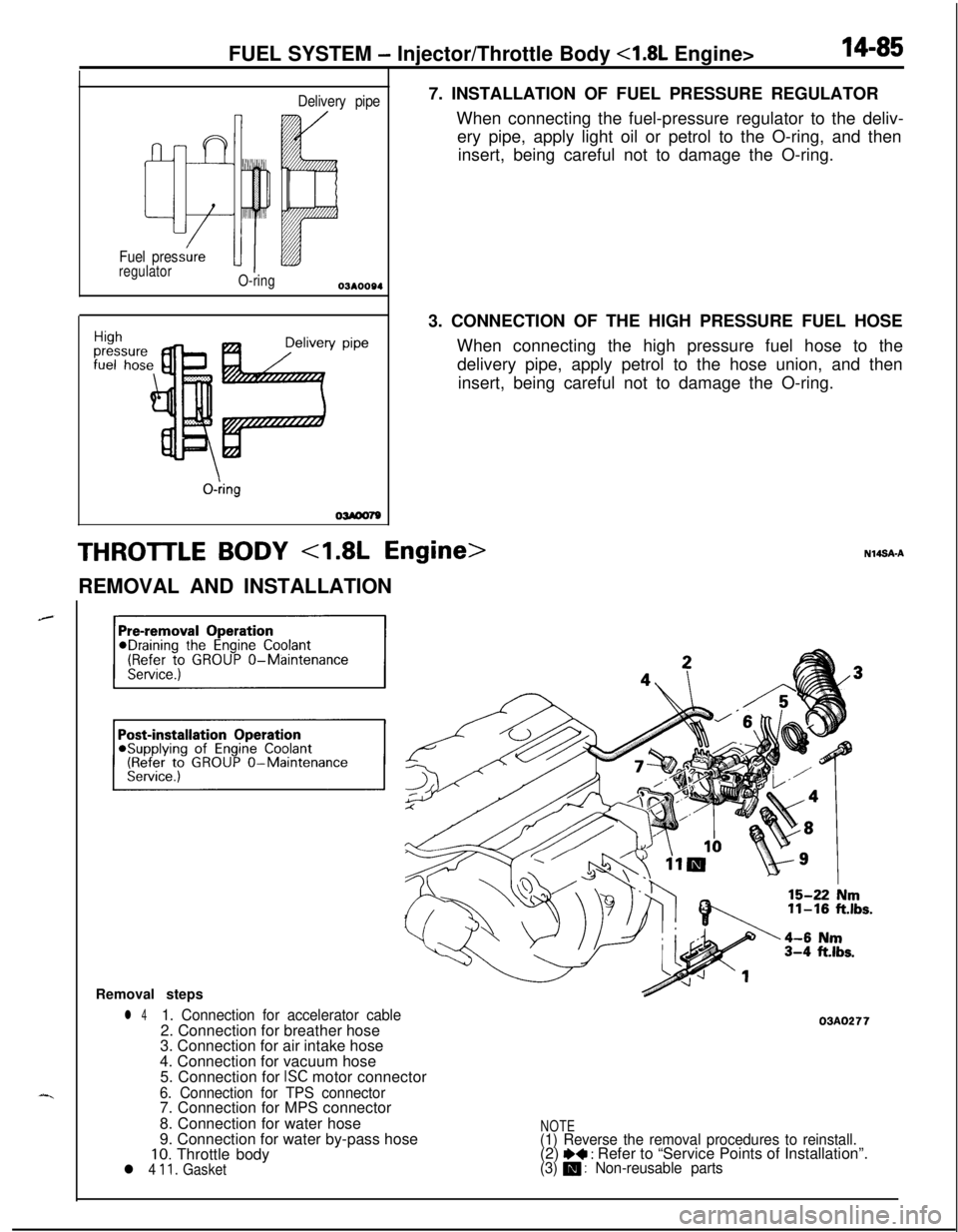
OWOO797. INSTALLATION OF FUEL PRESSURE REGULATOR
When connecting the fuel-pressure regulator to the deliv-
ery pipe, apply light oil or petrol to the O-ring, and then
insert, being careful not to damage the O-ring.
3. CONNECTION OF THE HIGH PRESSURE FUEL HOSE
When connecting the high pressure fuel hose to the
delivery pipe, apply petrol to the hose union, and then
insert, being careful not to damage the O-ring.
THROTTLE BODY 4.8L Engine>REMOVAL AND INSTALLATION
Removal steps
l 41. Connection for accelerator cable2. Connection for breather hose
3. Connection for air intake hose
4. Connection for vacuum hose
5. Connection for
ISC motor connector
6. Connection for TPS connector7. Connection for MPS connector
8. Connection for water hose
9. Connection for water by-pass hose
10. Throttle bodyl 4 11. Gasket
03AO277
NOTE(1) Reverse the removal procedures to reinstall.(2) I)+ : Refer to “Service Points of Installation”.(3) m : Non-reusable parts