1991 MITSUBISHI ECLIPSE spring height
[x] Cancel search: spring heightPage 25 of 1216

INTRODUCTION AND MASTER TROUBLESHOOTING - :;k%ii::& and25
GENERAL DATA AND SPECIFICATIONSNOOHA-
OOAOl59
GENERAL SPECIFICATIONS
z-
A-l
.8L Engine1.8L Engine2.0L DOHC2.0L DOHCItems“Medium”“High”~%n?urbo):Tz%$
Vehicle dimensions
mm(in.)Overall length
14,330(170.5)4,330(170.5)4,330(I 70.5)4,330(170.5)Overall width
21,690(66.5)1,690(66.5)
1,690
(66.5)
1,690(66.5)Overall height
31,306(51.4)1,306(51.4)1,306(51.4)
1,306(51.4)Wheel base
4
2,470(97.2)2,470(97.2)2,470(97.2)2,470(97.2)Tread Front
5
1,465(57.7)
1,465(57.7)
1,465
(57.7)1,465(57.7)
Rear6
1,450(57.1)1,450(57.1)1,450(57.1)1,450(57:l i
Overhang Front
7950(37.4)950(37.4)950(37.4)
950(37.4)
Rear
8
910(35.8)910(35.8)910(35.8)910(35.8)Minimum running ground
9
160(6.3)160(6.3)
160(6.3)160(6.3)clearancemm (in.)
Angle of approach
degrees10 15.3”15.3”15.3”
15.3”Angle of departure
degrees11 18.1”
18.1” ’18.1“
18.1”Vehicle weight
kg (Ibs.)
Curb weights
M/T
1,145(2,524)
1,165(2,568)
1,215
(2,679)
1,245(2,745)
AIT1 ,I 70(2,579)
1,190(2,623)
1,240
(2,734)
1,280(2,822)Gross vehicle weight rating
1,585(3,494)1,585(3,494)
1,630
(3,594)‘I ,670(3,682)Gross axle weight rating
Front
900(1,984)900(1,984)930(2,050)965(2,127)
Rear
685(1,510)685(1,510)
700
(1,543)705‘(1,554)Seating capacity
4
444
EngineModel No.
4G3746374G634G63
TransaxleModel No.
Manual transaxle
F5M22F5M22F5M22F5M33Automatic transaxle
F4A22F4A22F4A22F4A33
Clutch
TypeDry-single discDry-single discDry-single discDry-single disc& diaphragm& diaphragm& diaphragm& diaphragm
springspringspringspring
Page 144 of 1216

5-4BRAKES - Specifications
SERVICE SPECIFICATIONS
NO5CB-
ItemsSpecifications
Standard value
Brake pedal heightmm (in.) 176-181 (6.9-7.1)
Brake pedal free playmm (in.) 3-8
(l-.3)Brake pedal to floorboard clearance
mm (in.) 80 (3.1) or more
Parking brake lever stroke
5-7 notches
Output pressure proportioning valve
MPa (psi)
Split point
Output pressure [input pressure]
N (Ibs.) [Nm (ftlbs.)]70 (15) or less [4 (3) or less1Booster push rod to master cylinder piston clearance
mm (in.)
9 inch brake booster
0.8-l .O (.031-,039)
7
+8 inch brake booster0.5-0.7 (.020-.028)
Speed sensor’s internal resistance
kQ 0.8-l .2*
Clearance between the speed pole piece and
the toothed rotor
mm (in.)
0.3-0.9 (.012-,035)”Limit
Left/right proportioning valve out pressure difference
MPa (psi)0.4 (57)
Disc brake pad thickness
mm (in.) 2.0 (08)
Front disc thickness
mm (in.) 22.4 (882)
Rear disc thickness
mm (in.) 8.4
(.331)Disc
runoutmm (in.) 0.08 (.0031)Hub end play
mm (in.) 0.008
(.00031)
NOTE
*: Vehicles with ABS
TORQUE SPECIFICATIONS
ItemsNmft.lbs.
Pedal support bracket installation bolts
8-12
6-9
Pedal support bracket installation nut
IO-157-11
Pedal rod to pedal support bracket
17-26
12-19
Pedal rod to clutch pedal bracket
17-26
12-19
Clutch pedal bracket installation bolt
8-12
6-9
Turn-over spring mounting bolt
17-26
12-19
Stop lamp switch mounting nut
IO-157-l 1‘Clutch master cylinder installation nuts
10-157-11
Clutch pedal installation nut
20-2514-18
Lever assembly (A) installation nut
20-2514-18
Lever assembly
(B) installation nut20-2514-18
Page 232 of 1216

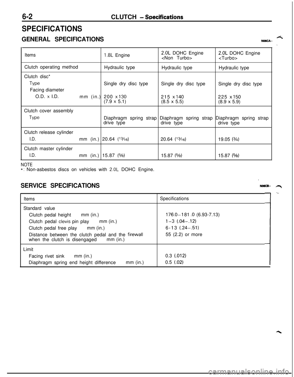
6-2CLUTCH - SDecifications
SPECIFICATIONS
GENERAL SPECIFICATIONS
Items1.8L Engine2.0L DOHC Engine
Clutch operating method
Hydraulic type
Hydraulic type
Hydraulic type
Clutch disc*
TypeSingle dry disc type
Single dry disc type
Single dry disc type
Facing diameter
O.D.
x I.D.
mm (in.) 200 x 130215 x 140225 x 150(7.9 x 5.1)
(8.5 x 5.5)
(8.9 x 5.9)
Clutch cover assembly
TypeDiaphragm spring strap Diaphragm spring strap Diaphragm spring strap
drive type
drive type
drive type
Clutch release cylinder
I.D.mm (in.) 20.64 (13/16)20.64 (13/6)19.05 (3h)Clutch master cylinder
I.D.mm (in.) 15.87 (%)15.87 (%)15.87 (543)
NOTE*: Non-asbestos discs on vehicles with 2.0L DOHC Engine.
SERVICE SPECIFICATIONS
Items
Standard valueClutch pedal heightmm (in.)
Clutch pedal
clevis pin playmm (in.)
Clutch pedal free playmm (in.)
Distance between the clutch pedal and the firewall
when the clutch is disengagedmm (in.)
Limit
Facing rivet sinkmm (in.)
Diaphragm spring end height differencemm (in.)
NO6lX- .H,
Specifications
176.0-I 81 .O (6.93-7.13)
l-3 (.04-.12)6-13 (.24-.51)
55 (2.2) or more
0.3 (012)
0.5
(.02)L-
Page 234 of 1216

6-4CLUTCH - Troubleshooting
TROUBLESHOOTINGNO6hi.J
SymptomProbable causeRemedy
Clutch slipsInsufficient clutch pedal playAdjust
Excessive wear of clutch disc facingReplace
Hardening of clutch disc facing, or adhesion of oilReplace
Clutch release fork catchingRepair or replace parts
Weak or damaged diaphragm spring
Replace
Clogging of hydraulic systemRepair or replace parts
Gear shift malfunctionExcessive clutch pedal playAdjust
Distorted clutch disc, excessive oscillation
Replace
Clutch cover assembly wornReplace
Clutch disc spline worn or corrodedReplace
Clutch disc facing peelingReplace
Clutch release bearing wornReplace
Damaged pressure plate or flywheelReplace
Leakage, air introduction or clogging of hydraulic systemRepair or replace parts
Clutch noiseInsufficient clutch pedal playAdjust
Improper installation of clutch cover assemblyRepair or replace parts
Excessive wear of clutch disc facing
Replace
Clutch release fork catchingRepair or replace parts
Clutch release bearing worn
Replace
Weak or damaged torsion springReplace
Damaged pilot bushingReplace
Insufficient lubrication of bearing sleeve sliding surfaceRepairClutch pedal feels “heavy”
Insufficient lubrication of clutch pedalRepairInsufficient lubrication of clutch disc spline
Repair
Clutch release fork catchingRepair or replace parts
Insufficient lubrication of bearing sleeve sliding surface
Repair
Clutch chattersWorn or damaged clutch disc facingReplace
Oil adhered to clutch disc facingReplace
Uneven height of diaphragm springRepair or replace parts
Weak or damaged torsion spring
Replace
Damaged pressure plate or flywheelReplace
Loose or damaged mountingReplace or tighten
mounting
Page 247 of 1216

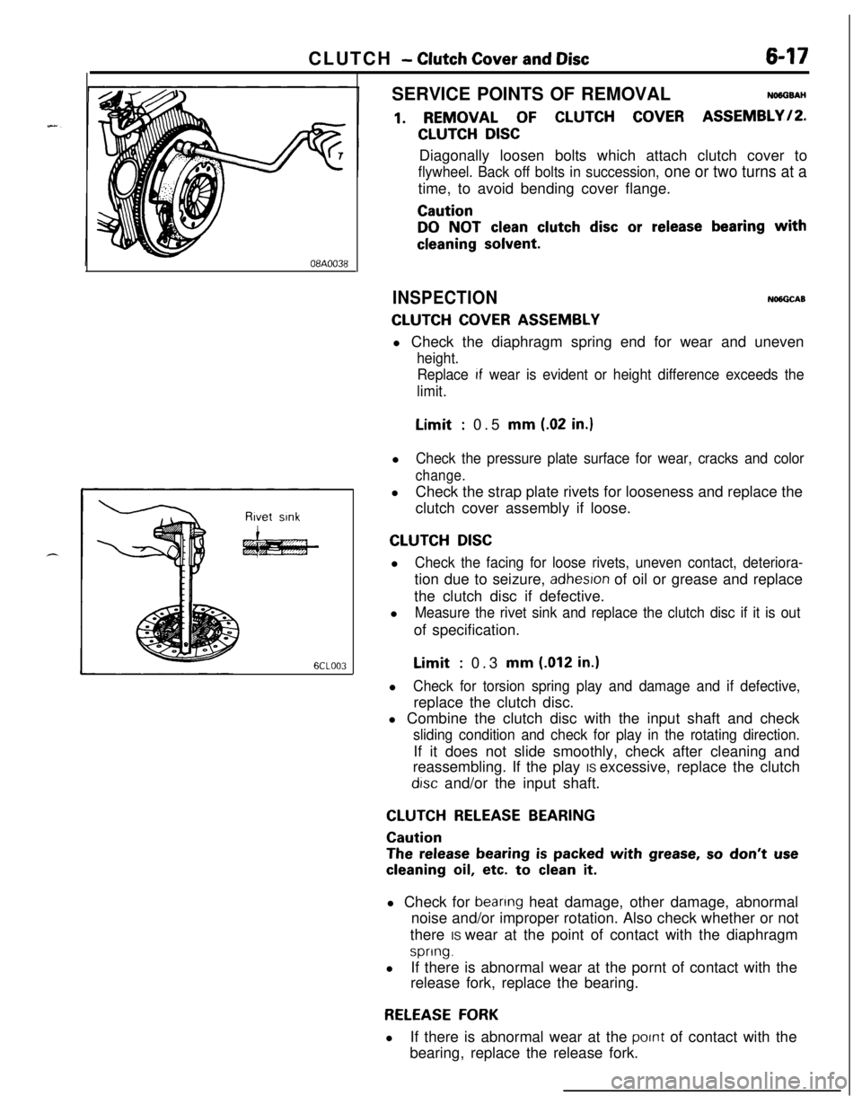
CLUTCH - Clutch Cover and Disc647
08A0038
6CLOO3SERVICE POINTS OF REMOVAL
NO6OSAH
1. REMOVAL OF CLUTCH COVER ASSEMBLY/P.
CLUTCH DISCDiagonally loosen bolts which attach clutch cover to
flywheel. Back off bolts in succession, one or two turns at atime, to avoid bending cover flange.
Caution
DO NOT clean clutch disc or release bearing with
cleaning solvent.
INSPECTIONNlNGCAB
CLUTCH COVER ASSEMBLYl Check the diaphragm spring end for wear and uneven
height.
Replace
If wear is evident or height difference exceeds the
limit.Limit
: 0.5 mm (.02 in.)l
Check the pressure plate surface for wear, cracks and color
change.lCheck the strap plate rivets for looseness and replace the
clutch cover assembly if loose.
CLUTCH DISCl
Check the facing for loose rivets, uneven contact, deteriora-tion due to seizure,
adhesron of oil or grease and replace
the clutch disc if defective.
l
Measure the rivet sink and replace the clutch disc if it is outof specification.Limit
: 0.3 mm (.012 in.)l
Check for torsion spring play and damage and if defective,replace the clutch disc.
l Combine the clutch disc with the input shaft and check
sliding condition and check for play in the rotating direction.If it does not slide smoothly, check after cleaning and
reassembling. If the play IS excessive, replace the clutch
drsc and/or the input shaft.
CLUTCH RELEASE BEARING
Caution
The release bearing is packed with grease, so don’t use
cleaning oil, etc. to clean it.l Check for
beanng heat damage, other damage, abnormal
noise and/or improper rotation. Also check whether or not
there IS wear at the point of contact with the diaphragm
spring.lIf there is abnormal wear at the pornt of contact with the
release fork, replace the bearing.
RELEASE FORKlIf there is abnormal wear at the
pornt of contact with the
bearing, replace the release fork.
Page 293 of 1216

ENGINE - SpecificationsItems
Valve stem to valve guide clearance
Intake
Exhaust
Valve guide
Lengthmm (in.)
Intake
Exhaust
Service size
mm (in.)mm (in.)Standard Value
0.03-0.06 (.0012-.0024)
0.05-0.09 (.0020-.0035)44 (1.73)
48 (1.89)
0.05
(.002), 0.25 (.OlO),
0.50
i.020) oversizeLimit
0.10
f.004)0.15
i.006)Valve seat
Width of seat contactmm (in.)
Seat angle
Valve spring
Free lengthmm (in.)
Load
N (Ibs.)
Out of squarness
Cylinder block
Cylinder boremm (in.)
ZIut-of;yundness and taper of cylinder bore
Cylinder block heightmm (in.)
Flatness of gasket surfacemm (in.)qight silent shaft
Front journal diametermm (in.)
Rear journal diametermm (in.)
Oil clearancemm (in.)
Front journal
Rear journal
-eft silent shaft
Front journal diametermm (in.)
Rear journal diametermm (in.)
Oil clearancemm (in.)
Front journal
Rear journal
‘istonO.D.mm (in.)
Clearance (Piston to cylinder)mm (in.)
0.9-l .3 (.0354-.0512)
44”-44.549.2
(1.937)48.2 (1.898)
274.6 (62) at installed height
Less than 2”4”
80.6 (3.173)
Less than 0.01
(.0004)285.2
(11.228)Less than 0.05
(.0020)0.1 (.0039)38.959-38.975
(1.5338- 1.5344)
35.951-35.967
(1.4154- 1.4160)
0.030-0.061(.0012-.0024)
0.050-0.091(.0020- .0036)
18.467- 18.480(.7270- .7276)
35.951-35.967(1.4154-1.4160)
0.020-0.054 (.0008-.0021)
0.050-0.091 (.0020-.0036)80.6
(3.173)
0.01-0.03 (.0004-.0012)
Page 294 of 1216

9-10ENGINE - SpecificationsItems
rIvrs,iz; rework dimension of valve seat hole
Intake0.3
(012) O.S.0.6
(024) O.S.
Exhaust 0.3
(.012) O.S.
0.6
(024) OS.Oversize rework of valve guide hole
(both intake and exhaust)mm (in.)
0.05
(.002) O.S.0.25
(.OlO) O.S.
0.50
(.020) O.S.Standard Value
43.300-43.325
(1.7047- 1.7057)
43.600-43.625
(1.7165-1.7175)
37.300-37.325(1.4685- 1.9695)
37.600-37.625(1.4803- 1.4813)
13.050- 13.068(.5138-.5145)
13.250- 13.268(.5217-.5224)
13.500-13.518
(.5315-.5322)Limit
Camshaft
Cam heightmm (in.)
Intake35.91 (1.4138)35.41 (1.3941)
Exhaust35.91 (1.4138)35.41 (1.3941)
Journal O.D.mm (in.)
33.935-33.950(1.3360- 1.3366)Bearing oil clearancemm (in.)
0.05-0.09 (.0020-.0035)End playmm (in.)
0.1-0.2 (.004-,008)Rocker arm
I.D.mm (in.)
18.910- 18.928
(.7445- .7452)Clearance (Rocker arm to shaft)mm (in.)
0.01-0.04 (.0004-.0016)0.1 (004)Rocker arm shaft
O.D.mm (in.)
18.885- 18.898(.7435-.7440)Rocker arm shaft spring
Free lengthmm (in.)
Intake
Exhaust
Valve
Valve lengthmm (in.)
Intake
Exhaust
Stem
O.D.mm (in.)
Face angle
Thickness of valve head (Margin)
Intake
Exhaust53.3
(2.098)53.3
(2.098)109.8 (4.323)
108.7 (4.280)
8
(.31)
45”-45.5”mm (in.)
1 .o
(.039)0.7 (028)0.7
(.028)0.5 (.020)
Page 299 of 1216

ENGINE - Specifications9-15ItemsStandard ValueLimit
Valve spring
Free lengthmm (in.)48.3
(1.902)47.3 (1.862)
Load
N (Ibs.)300 (66) at installed height
Out of squarnessLess than 1.5”4”
Cylinder block
Cylinder boremm (in.)85.00 (3.3465)
FIu-o$xrndness and taper of cylinder boreLess than 0.01 (0004)Flatness of gasket surfacemm (in.)Less than 0.05
(.0020)0.1 (.0040)Right silent shaft
Front journal diameter
mm (in.)
41.959-41.975(1.6519-1.6526)
Rear journal diameter
mm (in.)
40.951-40.967(1.6122-1.6129)
Oil clearancemm (in.)
Front journal
0.020-0.061 (.0008-.0024)Rear journal
0.050-0.091 (.0020-.0036)Left silent shaft
Front journal diameter
mm (in.)
18.467- 18.480(.7270-.7276)Rear journal diameter
mm (in.)
40.959-40.975
(1.6126-1.6132)Oil clearancemm (in.)
Front journal
0.020-0.054 (.0008-.0021)Rear journal
0.042-0.083 (.0017-.0033)Piston
O.D.
mm (in.)85.00 (3.3465)
CnlIr;;y (Piston to cylinder)(Non-Turbo) 0.02-0.04 (.0008-.0016)(Turbo)
0.03-0.05 (.0012-.0020)Ring groove width
mm (in.)
No. 11.22-l .24 (.0480-.0488)
No.21.52- 1.54 (.0598-.0606)Oil
3.01-3.03 (.1185-.1193)Service sizemm (in.)0.25
(.OlO), 0.50 (.020),0.75
(.030), 1 .oo i.039)oversize‘iston ring
Side clearancemm (in.)
No.1. No.2End gapmm (in.)
No. 1No. 2
Oil ring side railmm (in.)
Service sizemm (in.)
0.03-0.07 (.0012-.0028)
0.25-0.45 (.0098-.0177)
0.35-0.50 (.0138-.0197)
0.20-0.70 (.0079-.0276)0.25
(.OlO), 0.50 (.020),0.75 (030). 1.00 i.039)oversize0.1
(.004)0.8
(.031)0.8
(.031)1.0
(.040)