1991 MITSUBISHI ECLIPSE tires
[x] Cancel search: tiresPage 1 of 1216

BACKUPGROUP INDEX &ma
;r Service Manual
LASER
TALON
1991
Volume-l
Engine, Chassis
& Body
FOREWORDThis Service Manual has been prepared with the
latest service information available at the time of
‘* publication.It is subdivided into various group
categories and each section contains diagnosis,
disassembly, repair, and installation procedures
along with complete specifications and tightening
references. Use of this manual will aid in properly
performing any servicing necessary to maintain or
restore the high levels of performance and reliabilitydesigned into these outstanding vehicles.
This BACKUP DSM manual IS to be used ONLY as a BACKUP. Please DO NOT REDISTRIBUTEWHOLE SECTIONS. This BACKUP was sold to you under the fact that you do indeed OWNa GENUINE DSM MANUAL. It CANNOT BE considered a REPLACEMENT (Unless your originalmanual was lost or destroyed.)Please See
README.N or README.HTML for additional information
Thank you. G~mm~emymanual@hotma~l.com
1,
wA
CHRYSLER
CORPORATION
Chrysler Corporation reserves the right to make changes in design 0’: tomake additions to or improvements in its products without lmqoslngd ., . any obligations upon itself to install them on its products previouslymanufactured.
0 1990 Mitsubishi Motors CorporationPrinted in U.S.A.Introduction and
Master
Troubleshooting. . . . . .,. . . . . . . . . r...m,
Lubrication and Maintenance . . . . . . . . ‘-0‘8
; “. i,
.Front Suspension. . . . . . . . . . . . . . ..*............d...Rear Axle
. . . . . . . . . . . . . . . . . . . . . . . . . . . . ..‘.....................
/
ServiceBrakes-Parking. . . . . . . . . . . . . . . . . . . . . . . . . . . . . . . . . . . . . .
Clutch. . . . . . . . . . . . . . . . . . . . . . . . . . . . . . . . . ..~......................‘t.
Cooling. . . . . . . . . . . . . . . . . ..i....................................
,., .‘,-,
Engine..i....~....r...............~....~.*,.~.~.~,‘~~...;..~~..Intake and Exhaust
. . . . . . ..L....................Fuel System
. . . . . . . . . . . ..ti.......r................~...Propeller Shaft
.......................................IRear
Suspensiori.............................y.f...
ManualSteering- Power.....................................Manual
I
transaxle-Automatic .............:;i...,;.....;Wheels
and Tires.................................
Body.............................................................Heater & Air Conditioning
..............Emission
Contr6l Systems..............
INOTE: For Electrical, refer toVolume-2 “Electrical”.
Page 24 of 1216

24 INTRODUCTION AND MASTER TROUBLESHOOTING - fSo%k%:~~it’ndrU~ionsREAR WHEEL MEASUREMENTS
After placing the rear wheels on the brake tester, follow the
same procedures as for the front wheel measurements.
,’
~.Braking force of AWD models with VCU
Balancing
machine
Pick-up stand
WA0024
Braking force
EachwheelLeft/right
sumLeft/right
differenceAt
90kg (19860% or more ofIbs.) pedal de-front axle weightpression force
Rear wheels: 330
kg (727 Ibs.) or more8% or less of axle weight
TotalAt 90kg (198830 kg (1,829 Ibs.)
Ibs.) pedal de-or more*pression force
* About 20 kg (44 Ibs.) of force by viscosity torque has been
added.
or...
I
Braking-stop distanceAt primary velocity of 50 km/h
(31 mph): Within 16.0m (52.5 ft.)
WHEEL BALANCE.r=lFRONT WHEEL MEASUREMENTS
1. Jack up the rear wheels, and place an axle stand at the
designated part of the side sill.
2. Jack up the front wheels and set a pick-up stand and
balancing machine in place.
Caution
1.Set so that the front and rear of the vehicle are at
the same height.
2. Release the parking brake.
3. Rotate each wheel manually and check to be sure
that there is no dragging.
3. Use the engine to drive the tires, and then make the
measurement.Caution
1.If an error is indicated in the state of engine drive,
motor drive can be used concurrently.
2. Do not operate the clutch
suddenly, or increase or
reduce speed suddenly during the work.
REAR WHEEL MEASUREMENTS
1. Jack up the front wheels, and place an axle stand at the
designated part of the side sill.
2. Jack up the rear wheels, and then, after setting a pick-up
stand and balancing machine in place, follow the same
procedure as for front wheel measurements.
.&,
Page 31 of 1216

INTRODUCTION AND MASTER TROUBLESH’OOTING .- Master ~pAi&oOti~31POOR FUEL MILEAGE
../, *,, /S./..‘, _I, #_.a,‘.rr?
Symptom
Poor fuel mileageProbable cause
Fuel leak
Air cleaner clogged.Ignition system problems
Reference page or remedy”Repair as necessary.
-8-169
IFuel injection system problems.I-ICompression too low.9-23
Tires improperly inflated.22-3
Clutch slips.6-4
Brakes drag.5-7I
NOISE
Symptom
NoiseProbable cause
Loose bolts and nuts.
Engine noiseReference page or remedy
Retighten as necessary
9-23
’
HARD STEERING
Symptom
Hard steeringProbable causeLoose power steering oil pump belt
Low fluid levelAir in power steering system
Low tire pressure
Reference page or remedy19-12
Replenish19-13
22-3
Excessive turning resistance of lower arm ballExcessively tightened of steering gear box
IImproper front wheel alignment2-8
Excessive turning resistance of tie-rod ballioint2-35
1 i-23.30
19-8.10Sticky flow control valve
Bent rack in steering gear box‘.19-4119-23.30
POOR RETURN OF STEERING WHEEL TO CENTERSymptom
1Probable causeIReference pageI
Poor return of steering wheel tocenterImproper front wheel alignment
2-8
Improper tire pressure22-3
Excessive tightened rack support cover19-23.30
I-- ~~~Damaged front wheel bearingI2-12I
Page 33 of 1216

INTRODUCTION AND MASTER TROUBLESHOOTING - Master Troubleshooting
VEHICLE PULLS TO ONE SIDE
Symptom
Vehicle pulls to one sideProbable causeReference pageI
Improper front or rear wheel alignment
lmbalanced or worn tires
Uneven tire pressure2-817-3,2022-3
Excessive turning resistance of lower arm ball2-35
joint
Wheel bearing seizureReplace
Broken or weak coil spring2-29
Bent front axle drive shaft
2-15,3-13
Deformed lower arm2-35
STEERING WHEEL SHIMMY
SymptomSteering wheel shimmy
L
Probable cause
Improper front or rear wheel alignmentReference page or remedy2-8
17-3,20
Improper tire pressure22-3
lmbalanced wheelsReplace
Poor turning resistance of lower arm ball joint2-35
Excessive play of steering wheel
19-7,lO
Broken or weak front stabilizer2-33
Worn lower arm bushing2-33
Malfunctioning shock absorber2-29
17-8,32
Broken or weak coil spring
Wear, play, or seizure of wheel bearing
Wear, play, or seizure of drive shaft ball joint
Replace
2-15.3-13
BOTTOMING
I-SvmotomProbable cause1 Reference page or remedy[Bottoming
Overloaded vehicle
Broken or weak coil springMalfunctioning shock absorberCorrect2-29
l7-8,32
Page 109 of 1216

REAR AXLE - Troubleshooting3-7
Symptom
NOTE
1 Probable cause1 Remedy
In addition to a malfunction of the differential carrier components, abnormal noise can also be caused by the universal
joint of the propeller shaft, the axle shafts, the wheel bearings, etc. Before disassembling any parts, take all
possibilities into consideration and confirm the source of the noise.
Abnormal noise when
Damaged differential gears
ReplacecorneringDamaged pinion shaftInsufficient gear oil quantity
Replenish
Gear noiseImproper final drive gear tooth contact adjustmentAdjust or replace
Incorrect final drive gear backlashAdjust
Improper drive pinion preload adjustment
Damaged, broken, and/or seized tooth surfaces of
Replacethe drive gear and drive pinion
Damaged, broken, and/or seized drive pinion bear-
ings
NOTE
Damaged, broken, and/or seized side bearings
Damaged differential case
Inferior gear oilInsufficient gear oil quantity
Replenish
Noise from the engine, muffler vibration, transaxle, propeller shaft, wheel bearings, tires, body, etc., is easily mistaken
as being caused by malfunctions in the differential carrier components. Be extremely careful and attentive whenperforming the driving test, etc.
Test methods to confirm the source of the abnormal noise include:coasting acceleration, constant speed driving,
raising the rear wheels on a jack, etc. Use the method most appropriate to the circumstances.
Gear oil leakageWorn or damaged front oil seal, or an improperlyReplace
installed oil seal
Damaged gasket
Seizure
VOTE
Loose companion flange self-locking nut
Loose filler or drain plug
Clogged or damaged vent plug
Insufficient final drive gear backlash
Excessive drive pinion preload
Excessive side bearing preload
Insufficient differential gear backlash
Excessive clutch plate preload
Inferior gear oilInsufficient gear oil quantityRetighten or replace
Retighten or apply adhesive
Clean or replaceAdjust
Replace
Replenish
n the event of seizure, disassemble and replace the parts involved, and also be sure to check all components for any
rregularities and repair or replace as necessary.
3reak downIncorrect final drive gear backlashAdjustInsufficient drive pinion preload
Insufficient side bearing preload
Excessive differential gear backlash
Loose drive gear clamping boltsRetighten
VOTEn addition to disassembling and replacing the failed parts, be sure to check all components for irregularities and repairIr
replace as necessary.
The limited slip differentialThe limited slip device is damagedDisassemble, check the func-
lees not function (ontioning, and replace the dam-
;now, mud, ice, etc.)aged parts
Page 1039 of 1216

22-l-.
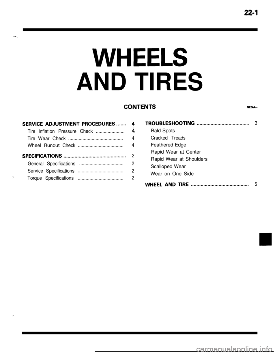
WHEELS
AND TIRES
CONTENTSNZZAA-
SERVICE ADJUSTMENT PROCEDURES.......4TROUBLESHOOTING......................................3
Tire
InflationPressureCheck......................4Bald Spots
TireWearCheck..........................................4Cracked Treads
Wheel
RunoutCheck...................................4Feathered Edge
SPECIFICATIONSRapid Wear at Center.............................................2
General
Specifications..................................2Rapid Wear at Shoulders
ServiceSpecificationsScalloped Wear...................................2Wear on One Side
7TorqueSpecifications...................................2
WHEEL AND TIRE..........................................5
Page 1040 of 1216

5 22-2WHEELS AND TIRES - Specifications
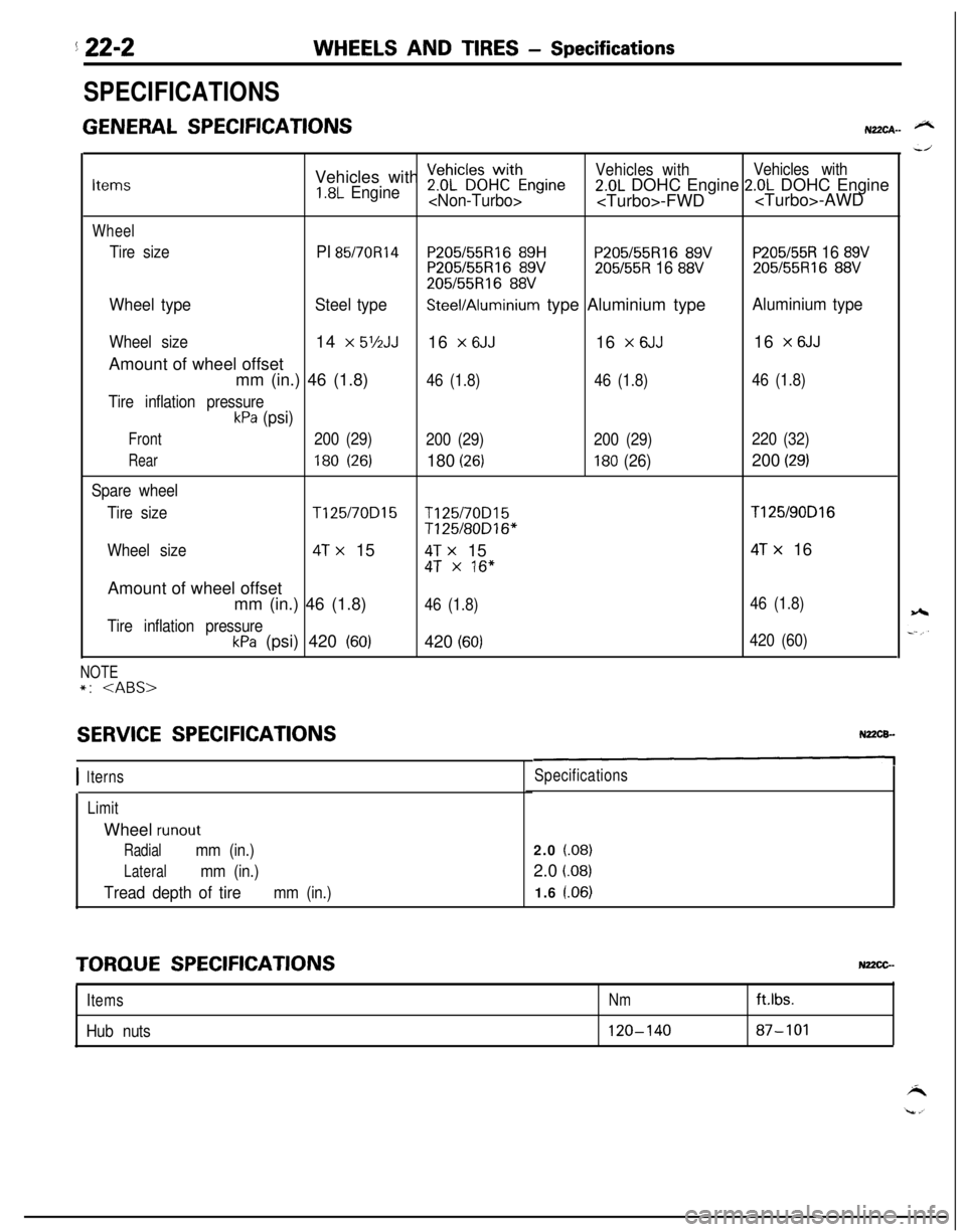
SPECIFICATIONS
GENERAL SPECIFICATIONSN22CA- @NVehicles with
~eDhL”~~HWCthEngineVehicles withVehicles withItems1.8L Engine2.0L DOHC Engine 2.0L DOHC Engine
Wheel
Tire sizePI 85/70R14P205155Rl6 89HP205/55R16 89VP205/55R 16 89VP205155R16 89V205/55R 16 88V205/55R16 88V
205/55R16 88V
Wheel typeSteel typeSteel/Aluminium type Aluminium typeAluminium type
Wheel size14 x 5’/2JJ16 x 6JJ16 x 6JJ16 x 6JJAmount of wheel offset
mm (in.) 46 (1.8)
46 (1.8)46 (1.8)46 (1.8)
Tire inflation pressure
kPa (psi)
Front200 (29)
200 (29)200 (29)220 (32)
Rear180 (26)180 (26)180 (26)200 (29)
Spare wheel
Tire size
T125/70D15T125/70D15T125/90D16
T125/80D16*
Wheel size
4T x 154T x 154T x 16
4T x 16”Amount of wheel offset
mm (in.) 46 (1.8)
46 (1.8)46 (1.8)
Tire inflation pressure
kPa (psi) 420 (60)420 (60)420 (60)
NOTE*:
SERVICE SPECIFICATIONS
I 1terns
LimitWheel
runout
Radialmm (in.)
Lateralmm (in.)
Tread depth of tiremm (in.)
Specifications2.0
(.08)2.0
i.08)1.6 l.06)
TORQUE SPECIFICATIONSNz2cG-
ItemsNm
Hub nuts120-140ftlbs.87-101
Page 1041 of 1216

WHEELS AND TIRES - Troubleshooting22-3
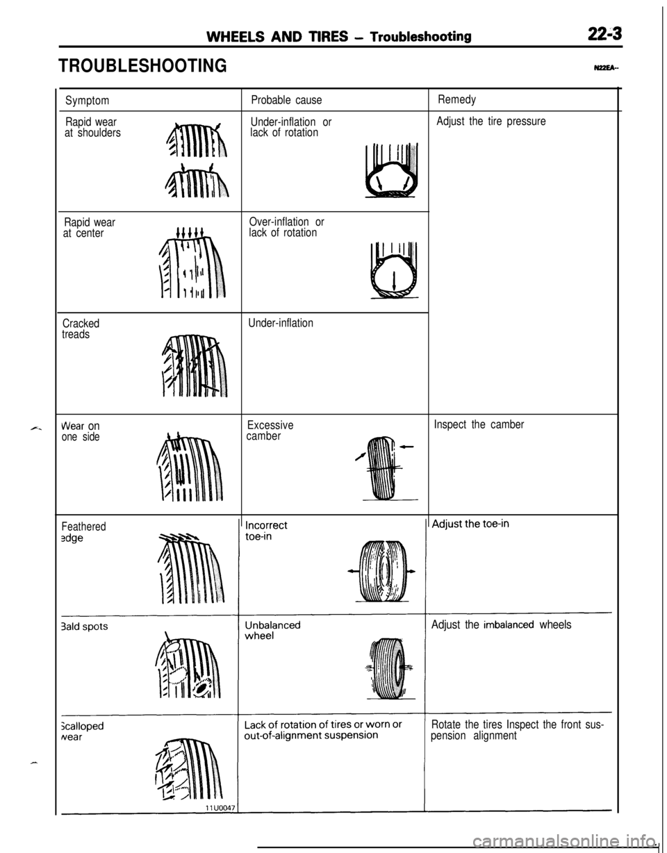
TROUBLESHOOTINGN22EA-
Symptom
Rapid wear
at shouldersProbable cause
Under-inflation or
lack of rotationRemedy
Adjust the tire pressure
Rapid wear
at centerOver-inflation or
lack of rotation
Cracked
treadsUnder-inflation
Wear onone side
Excessive
camberInspect the camber
Feathered
Adjust the imbalanced wheels
Rotate the tires Inspect the front sus-
pension alignment