1991 MITSUBISHI ECLIPSE Wires
[x] Cancel search: WiresPage 58 of 1216

z-10FRONT SUSPENSION - Hub and Knuckle
SERVICE POINTS OF REMOVAL
NOZIBAG2. REMOVAL OF DRIVE SHAFT NUT
6-eLoosen the drive shaft nut while the vehicle is on the floor
_ ,’with the brakes applied.
Front speedsensorPole piece
,4mx‘l4
J&14. DISCONNECTION OF FRONT SPEED SENSOR
Remove the mounting bolts which hold the speed sensor
bracket to the knuckle, and then remove the speed sensor.Caution
Be careful when handling the pole piece at the tip of
the speed sensor and the toothed edge of the rotor so
as not to damage them by striking against other parts.
5. REMOVAL OF CALIPER ASSEMBLY
Remove the caliper assembly and suspend it with wires.
8. DISCONNECTION OF LOWER ARM BALL JOINT
Using the special tool, disconnect the lower arm ball joint
from the knuckle.
Caution,*1. Be sure to tie the cord of the special tool to the
1nearby part.
2. Loose the nut but do not remove it.
IO. DISCONNECTION OF TIE ROD END
Using the special tool, disconnect the tie rod end from the
knuckle.
Caution1. Be sure to tie the cord of the special tool to the
nearby part.
2. Loose the nut but do not remove it.
11. REMOVAL OF DRIVE SHAFT
(1) Using the suitable tool to push out the drive shaft from
the front hub.
Page 186 of 1216

5-46BRAKES - Service Adjustment ProceduresWhen new
When worn
14G0017
14LO169
14A0403
\14AO400
FRONT DISC BRAKE PAD CHECK AND REPLACE-
MENiNWFOAF
NOTE
The brake pads have wear indicators that contact the brake discd’when the brake pad thickness becomes 2 mm
(.08 in.), and
emit a squealing sound to warn the driver.
1. Check brake pad thickness through caliper body check
port.Limit: 2.0 mm
(.08 in.)
Caution1. When the limit is exceeded, replace the pads at
both sides, and also the brake pads for the wheelson the opposite side at the same time.
2.If there is a significant difference in the thicknesses
of the pads on the left and right sides, check the
sliding condition of the piston, lock pin sleeve and
guide pin sleeve.
2.Remove lock or guide pin. Lift caliper assembly and retain
with wires.
Caution
Do not wipe off the special grease that is on the guide
-pin or allow it to contaminate the guide pin.
3. Remove the following parts from caliper support.
=Qg@-(4)
(1)
(2)
(3)
(4)Pad and wear
indicator assembly
Pad assembly
Outer shimPad clips
-4. Measure hub torque with pad removed to measure brake
drag torque after pad installation.
NOTETighten the nuts in order to secure the disc to the hub.
5. Securely attach the pad clip to the caliper support.a
Page 188 of 1216

5-48BRAKES - Service Adjustment Procedures
14A0407FRONT BRAKE DISC RUN-OUT
CORRECTIO&wAB
1.If the run-out of the brake disc is equivalent to or exceeds 5the limit specification, change the phase of the disc and
-’hub, and then measure the run-out again.
(1) Before removing the brake disc, chalk both sides of the
wheel stud on the side at which run-out is greatest.
(2) Remove the brake disc, and then place a dial gauge as
shown in the illustration; then move the hub in the axialdirection and measure the play.
Limit: 0.008 mm
(00031 in.)
If the play is equivalent to or exceeds the limit,
disassemble the hub knuckle and check each part.
(3) If the play does not exceed the limit specification, and
then check the run-out of the brake disc once again.
Mount the brake disc on the position dislocated from
the chalk mark.
ei
2.If the run-out cannot be corrected by changing the phase-ofI’the brake disc, replace the disc.
REAR DISC BRAKE PAD CHECK AND REPLACE-MENT
NO5FUAD
1. Check brake pad thickness through caliper body check
port.Limit: 2.0 mm
(.08 in.)
Caution1. When the limit is exceeded, replace the pads at
both sides, and also the brake pads for the wheelson the opposite side at the same time.
2.If there is a significant difference in the thicknesses
of the pads on the left and right sides, check the
sliding condition of the piston, lock pin sleeve and
guide pin sleeve.
2.Loosen the parking brake cable (from the vehicle interior),
and disconnect the parking brake end installed to the rear
brake assembly.
A
3.Remove lock pin. Lift caliper assembly and retain with -‘wires.
Caution
Do not wipe off the special grease that is on the lockpin or allow it to contaminate the lock pin.
Page 520 of 1216

14-66FUEL SYSTEM -MPI System Inspection 4.8L Engine>
6FU1253
-1 Batterv
I6FUO751
03AOO50
03AOO57(3) Connect
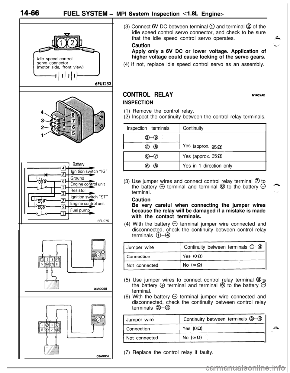
6V DC between terminal @ and terminal @ of the
idle speed control servo connector, and check to be sure
that the idle speed control servo operates.
CautionApply only a 6V DC or lower voltage. Application of
higher voltage could cause locking of the servo gears.
(4)
If not, replace idle speed control servo as an assembly.
CONTROL RELAY
INSPECTION
NWWAE(1) Remove the control relay.
(2) Inspect the continuity between the control relay terminals.
Inspection terminalsContinuity
l---$+-l Yes (approx. 9552)
B-0
@-@
~~~
Yes (approx. 35Q)
Yes in 1 direction only(3) Use jumper wires and connect control relay terminal
@ to
the battery
@ terminal and terminal @ to the battery @
terminal.Caution
Be very careful when connecting the jumper wires
because the relay will be damaged if a mistake is made
with the contact terminals.
(4) With the battery
0 terminal jumper wire connected and
disconnected, check the continuity between control relay
terminals @-@I.
Continuity between terminals 0-B(5) Use jumper wires to connect control relay terminal
@I to
the battery
@ terminal and terminal @ to the battery 0
terminal.(6) With the battery
0 terminal jumper wire connected and
disconnected, check the continuity between control relay
terminals @-@I.
Continuity between terminals 0-a
1(7) Replace the control relay if faulty.
Page 532 of 1216

FUEL SYSTEM - MPI System Inspection <2.0L DOHC Engine>
6FUO999
Accelerator pedal
DepressedContinuity .
Non-conductive
(03 fl)
ReleasedIConductive (0 fl)I(4) Replace the idle position switch if faulty.
NOTE
For replacement procedure, refer to the idle position switch(fixed speed adjusting screw) adjustment section
(P.14-
52.).OXYGEN SENSOR
NllQDeJ
INSPECTION(1) Disconnect the oxygen sensor connector.
(2) Check that there is continuity [approx. 12
52 at 20°C (68”F)l
between oxygen sensor connector terminal @ and terminal
GO.(3) If there is no continuity, replace the oxygen sensor.
(4) Warm up the engine until the engine coolant temperature
exceeds
80°C (176°F).(5) Use jumper wires to connect oxygen sensor terminal
@and terminal
@ to the battery @ terminal and 0 terminal.
Caution
Be very careful when connecting the jumper wires
because the oxygen sensor will be damaged if a
mistake is made in the connecting terminals.
(6) Connect a digital voltmeter between terminal
@ and
terminal
0.(7) While repeatedly racing the engine, measure the ‘output
voltage of the oxygen sensor.
When racing
engineWhen the
air/fuel mixture raticINSTALLATION
1. For removal and installation of oxygen sensor, refer to
GROUP 11
- Exhaust Manifold.
2. Oxygen sensor tighten to specified torque.
Specified torque: 40
- 50 Nm (29 - 36 ft.lbs.)
Page 535 of 1216

_-
FUEL SYSTEM - MPI System Inspection <2.0L DOHC Engine>'I4181
OlLO22Z
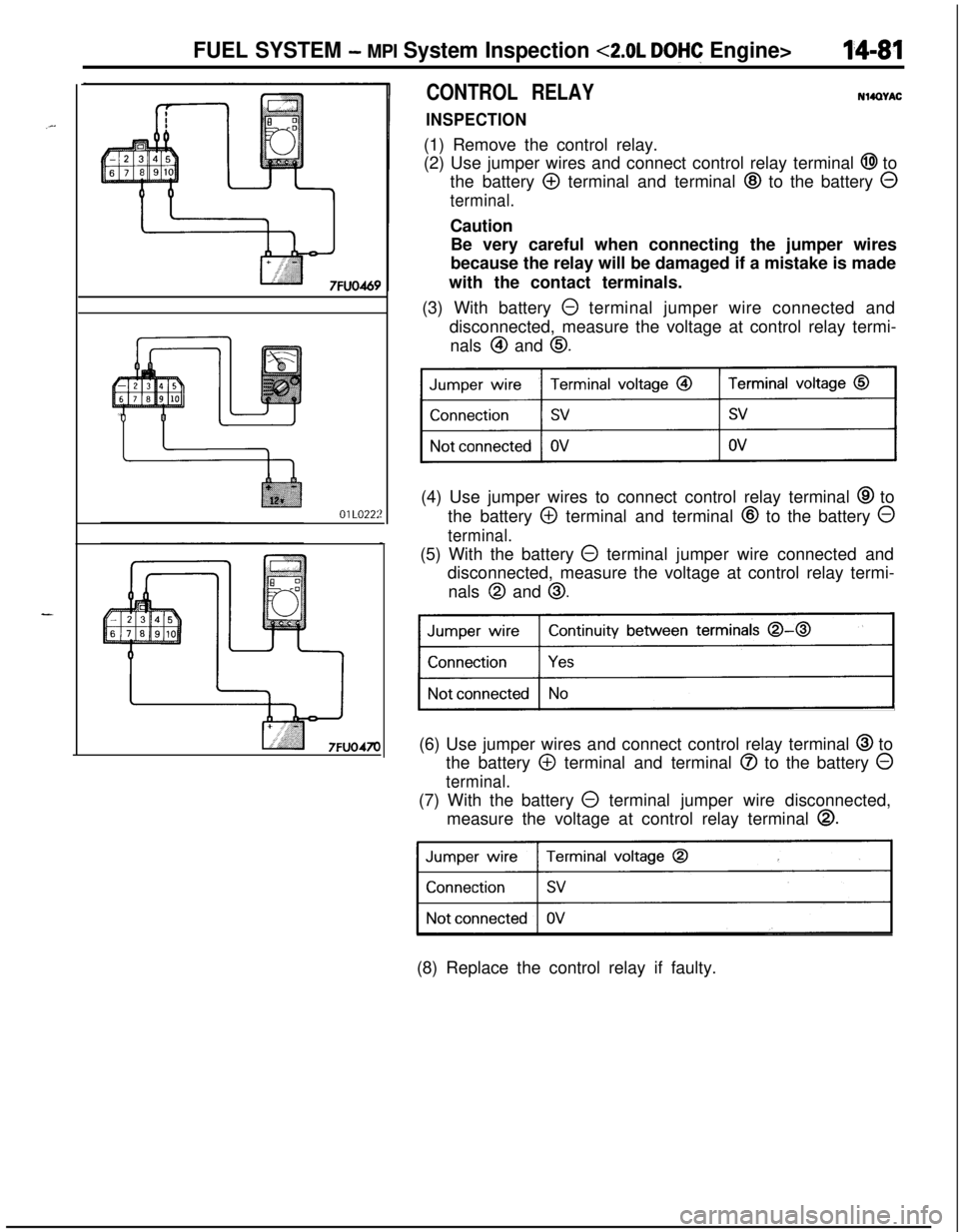
CONTROL RELAY
INSPECTIONNWWAC
(1) Remove the control relay.
(2) Use jumper wires and connect control relay terminal
@I to
the battery
@ terminal and terminal @ to the battery 0
terminal.Caution
Be very careful when connecting the jumper wires
because the relay will be damaged if a mistake is made
with the contact terminals.
(3) With battery
0 terminal jumper wire connected and
disconnected, measure the voltage at control relay termi-
nals
@I and 0.(4) Use jumper wires to connect control relay terminal
@ to
the battery
@ terminal and terminal @ to the battery 0
terminal.(5) With the battery
@ terminal jumper wire connected and
disconnected, measure the voltage at control relay termi-
nals
@I and 0.
Continuity between terminals 0-0
)(6) Use jumper wires and connect control relay terminal
@ to
the battery
@ terminal and terminal @ to the battery 0
terminal.(7) With the battery
0 terminal jumper wire disconnected,
measure the voltage at control relay terminal
0.
31(8) Replace the control relay if faulty.