1991 MITSUBISHI ECLIPSE crankshaft pulley
[x] Cancel search: crankshaft pulleyPage 251 of 1216

COOLING - Specifications7-3
TORQUE SPECIFICATIONSN07CG.
ItemsRadiator insulator
upperThermosensor to radiator
Automatic transaxle oil cooler hose cramp
Automatic transaxle oil cooler hose mounting bolt
Water outlet fitting bolts
Engine mount insulator nut (large)
Engine mount insulator nut (small)
Engine mount bracket to engine
Bracket between engine mount bracket and engine
Tension pulley bracket for air conditioner
<1.8L Engine>
Water pump installation bolt
Bolt head mark “4T”
Bolt head mark “7T”
Water pulley bolt
pumpDamper pulley, crankshaft pulley
<1.8L Engine>
<2.0L DOHC Engine>
Timing belt front upper cover installation bolt
Timing belt front lower cover installation bolt
Crankshaft sprocket installation bolt
Timing belt
B tensioner
Tension pulley bracket for air conditioner
<2.0L DOHC Engine>
Automatic tensioner installation bolt
Tensioner pulley installation bolt
Oil level
gaugeFront exhaust pipe to exhaust manifold
Exhaust manifold cover (A)
Flange bolt: 8
x 12 mm (.31 x .47 in.)
Washer assembled bolt: 6
x 14 mm (.24x.55in.)
<2.0L DOHC Engine (Non-Turbo)>
Exhaust manifold cover
(8)
Heat protecter (A)
Heat protecter
(B)
Exhaust manifold to cylinder head<1.8L Engine>
<2.0L DOHC Engine>
Engine hanger to engine bracket
JVater inlet pipe installation bolt
Transaxle side
Engine block side
<1.8L Engine>
<2.0L DOHC Engine>
'ower steering oil pump to oil pump bracket
‘ower steering oil pump bracket to engine
Nmft.lbs.
9-14
7-103-4
2-3
4-63-4
3-52-4
17-2012-14
60-8043-58
30-4022-29
50-6536-47
17-2612-19
18-2213-15
12-15
9-11
20-2714-20
8-106-7
15-18
11-13
20-3014-22
IO-127-9
10-127-9
110-13080-9415-22
11-16
23-27
17-20
20-2714-2043-55
31-4012-15
9-11
30-4022-29
40-6029-43
30-4022-29
27-33
20-24
8-106-7
12-15
9-11
12-15
9-11
12-15
9-11
12-15
9-l 1
15-2011-14
25-3018-22
12-15
9-11
43-55
31-40
IO-127-9
12-15
9-11
35-4525-33
25-3318-24
Page 269 of 1216

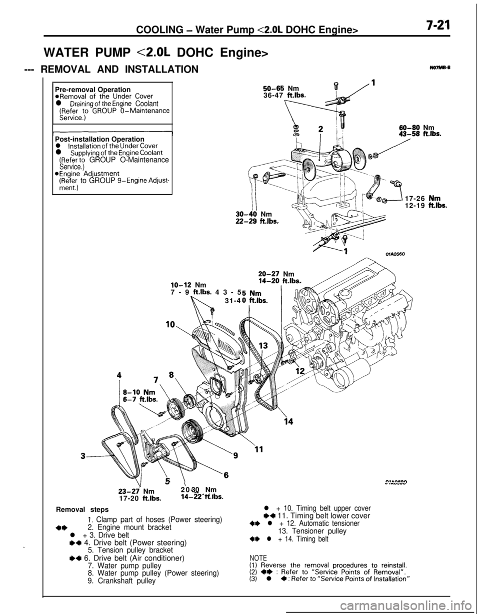
COOLING - Water Pump <2.0L DOHC Engine>7-21WATER PUMP <2.0L DOHC Engine>
--- REMOVAL AND INSTALLATION
No7Ms-B
_Pre-removal Operation
@Removal of the Under Coverl Draining of the Engine Coolant(Refer to GROUP O-MaintenanceService.)
50-65 Nm136-47 ft.lbs.
60-60 Nm
Post-installation Operation
l installation of the Under Coverl supplying of the Engine Coolant(Refer to GROUP O-MaintenanceService.)*Engine Adjustment
(Ri+&; to GROUP g-Engine Adjust-
lo-12 Nm
7-9 ft.lbs. 43-5
31-4
III-40 Nm!-29 ft.lbs.17-26
12-19OlAO560
20-27 Nm14-20 ft.lbs.
23-27 Nm
17-20 ft.lbs.
”20-’ 30 Nm” .““*wY--
-~ . .14-22 ft.ll3s.Removal steps
I. Clamp part of hoses (Power steering)
+*2. Engine mount bracket
l + 3. Drive belte+ 4. Drive belt (Power steering)5. Tension pulley bracket
I)4 6. Drive belt (Air conditioner)7. Water pump pulley
8. Water pump pulley (Power steering)
9. Crankshaft pulley
l + 10. Timing belt upper coverI)4 11. Timing belt lower cover+I) l + 12. Automatic tensioner13. Tensioner pulley
+I) l + 14. Timing belt
NOTE(1) Reverse the removal procedures to reinstall.(2) +e : Refer to “Service Points of Removal”.(3) l 4 : Refer to “Service Points of Installation”
,“k.
Page 302 of 1216

9-18ENGINE - Specifications
TORQUE SPECIFICATIONS
NO9CG-Items
Engine mount insulator nut (large)
(small)
Engine mount bracket nut or bolt
Transaxle mount insulator nut
Transaxle mount to body
Front roll stopper insulator nut
Front roll stopper bracket to centermember
Rear roll stopper insulator nut
Rear roll stopper bracket to centermember
Accelerator cable adjusting bolts
Fuel high pressure hose to delivery pipe
Ground cable to air intake manifold
Control wiring harness to air intake plenum
Power steering oil pump to bracket
Air conditioner to bracketcompressor
Exhaust pipe clamp bolt
Exhaust pipe to rubber hanger
Oil drain plug
panOil (bolts)
pan(nuts)VVater pulley
pump
Tensioner pulley bracket (air conditioner compressor)
Timing belt front coverCrankshaft sprocket
Camshaft sprocket
Timing belt “B” tensioner bolt
-eft engine support bracket3il switch
pressure3il unit
pressure gauge
Iii filter bracket
Iii cover
pumpqelief plug
‘lywheel or drive plate
ixhaust pipe bracket
support
‘rant roll stopper bracket
Iear roll stopper bracket‘rant engine bracket
support
:1.8L Engine>
Oil screen
Rocker cover
Camshaft bearing cap bolt (6 x 20)
(8 x 65)
Exhaust pipe to exhaust manifold
Intake manifold bolt
stay
Cylinder head bolt
Crankshaft pulley
Crankshaft damper pulleyNm
ftlbs.
60-8043-58
30-4022-29
50-6536-47
60-8043-58
40-5029-36
50-6536-47
40-5029-36
40-5029-36
40-5029-36
4-63-4
4-6
3-4
4-6
3-4
4-6
3-4
35-45
25-33
23-27
17-20
30-4022-29
10-157-l 135-45
25-33
6-84-6
5-73.5-5
8-106-7
23-27
17-20
10-127-9
110-13080-94
80-10058-72
15-2211-16
30-4222-308-126-9
8-126-9
15-2211-16
15-1811-13
40-5029-36
130-14094-101
30-4222-3055-75
40-54
110-13080-94
50-7036-51
18-2513-18
5-74-5
20-2714-2019-21
14-15
30-4022-29
18-2513-18
70-7551-5415-1811-13
15-1811-13
Page 303 of 1216

-
ENGINE - Specifications9-19Items
Oil sprocketpump
Silent shaft sprocket
Timing belt tensioner nut or bolt
Timing belt rear cover (upper)
(lower)
Oil drivenpump gear
Front case
Connecting rod bearing cap
Crankshaft bearingcap
<2.0L DOHC Engine>
Engine mount bracket to bracket nut or bolt
Engine cooler pipe to engine front case
Exhaust pipe to exhaust manifold (Turbo)
Oil return pipe to oil pan (Turbo)
Oil screen nut or bolt
Centermember installation bolt
Oil pipe to engine (Turbo)
Rocker cover
Center cover
Heat protector to exhaust manifold
Exhaust manifold to turbocharger(Turbo)
Intake manifold stay bolt
Cylinder head bolt
Crankshaft pulley
Oil sprocketpump
Silent shaft sprocket
Auto tensioner
Timing belt tensioner pulley
Timing belt idle pulley
Timing belt rear cover
Oil drivenpump gear
Front case
Engine oil cooler mounting nut
Eye bolt (Engine oil cooler side)
Engine oil hose mounting bolt
Engine oil feed hose assembly to Feed/Return tube assembly
Engine oil return hose assembly to Feed/Return tube assembly
Feed/Return tube assembly to oil filter bracket
Eye bolt (Oil filter bracket side)
Crankshaft angle sensor
Throttle body stayNm
ft.lbs.
34-4026-29
34-4025-29
22-3016-22
IO-127-9
12-159-11
34-4025-29
15-18
11-1332-3524-25
50-5537-39
17-26
12-19
40-4529-33
40-6029-43
8-106-7
15-2211-16
80-l 0058-72
14-19
10-142.5-3.52-3
2.5-3.52-3
12-15
9-l 155-65
40-47
25-3018-22
90-10065-72
20-3014-22
50-6036-43
43-49
31-35
20-2714-2043-55
31-4034-42
25-30
10-127-9
34-4025-29
20-2214-16
8-126-9
30-3522-25
3-52-4
40-5029-36
40-5029-36
3-52-4
40-4529-33
IO-137-9
15-2211-16SEALANTS AND ADHESIVES
NOSCE-.Items
Specified sealant
“. _
SemiWrcularMOPAR Part No.4318034Rocker cover
<2.0L
1(No.4318034No.1141~1
1 Oil pan1No.MD997110I
Page 325 of 1216

ENGINE <1.8L Engine> - Timing Belt
TIMING BELT
- REMOVAL AND INSTALLATION,
50-65 Nm
36-47 ft.lbs.Pre-removal Operation
@Removal of Under Cover
\ 16-22 ftlbs.\
lo-12 Nm
7-9 ft.lbs.
I28
15-22 Nm
11-16 ft.lbs.
3hO Nm
26-29 ft.lbs.
110-130 Nm(( \\ _ 60-94 ftlbs.
15-16 Nm-23-27 Nm
11-13 ft.lbs.17-20 ft.lbs.12-15 Nm
9- 11 ft.lbs.OlAO555
Removal steps
1. Clamp for pressure hose (power steering)
4*2. Engine mount bracketI)* 3. Drive belt (power steering)
4. Tensioner pulley bracket
H 5. Drive belt (air conditioner)
l + 6. Drive belt (alternator)
7. Water pump pulley (power steering)
8. Water pump pulley
9. Damper pulley
10. Adapter
11. Crankshaft pulley
I)4 12. Timing belt front upper cover
13. Gasket
l 14. Timing belt front lower cover
15. Gasket
16. Access cover
17. Crankshaft sprocket bolt
18. Special washer
Adjustment of timing belt tensioner
l *
:: 19. Timing beltl 4 20. Timing belt tensioner
I)+ 21. Tensioner spacer
l 22. Tensioner spring
23. Camshaft sprocket
4*24. Oil pump sprocket
25. Crankshaft sprocket
l 26. Flange
27. Timing belt tensioner “B”
~~ l 28. Timing belt “B”
l 4Adjustment of timing belt “B” tension
29. Right silent shaft sprocket
l * 30. Spacer
~~ 31. Crankshaft sprocket “B”32. Key
33. Left engine support bracket
34. Timing belt rear upper cover
35. Timing belt rear lower cover
NOTE(1) Reverse the removal procedures to reinstall.
(2)
4* : Refer to “Service Points of Removal”.
(3) l 4 : Refer to “Service Points of Installation”.
Page 328 of 1216

9-44ENGINE <1.8L Engine> - Timing Belt
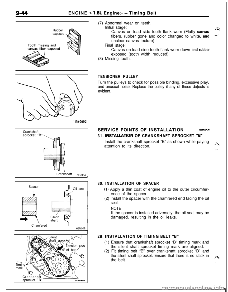
Rubber
exposedTooth missing and
1 EN0002
Crankshaftsprocket “6
Crankshaft 6EN304
Spacer
Chamfered
6EN009
J
TiGGrnmarkCrankshaft
\vsprocket “B”(7) Abnormal wear on teeth.
Initial stage:
Canvas on load side tooth flank worn (Fluffy canvas
afibers, rubber gone and color changed to white, and
-unclear canvas texture)
Final stage:Canvas on load side tooth flank worn down and rubber
exposed (tooth width reduced)
(8) Missing tooth.
TENSIONER PULLEYTurn the pulleys to check for possible binding, excessive play,
and unusual noise. Replace the pulley if any of these defects is
evident.”
SERVICE POINTS OF INSTALLATION
31. INSTALLATlON OF CRANKSHAFT SPROCKET “6”Install the crankshaft sprocket “B” as shown while paying
attention to its direction.
~,
‘d
30. INSTALLATION OF SPACER
(1) Apply a thin coat of engine oil to the outer circumfer-
ence of the spacer.
(2) Install the spacer with the chamfered end facing the oil
seal.
NOTEIf the spacer is installed adversely, the oil seal may be
damaged, resulting in the oil leaks.
28. INSTALLATION OF TIMING BELT “B”(1) Ensure that crankshaft sprocket “B” timing mark and
the silent shaft sprocket timing mark are aligned.
(2) Fit timing belt “B” over crankshaft sprocket “B” and
the silent shaft sprocket. Ensure that there is no slack inthe belt.+
a.
Page 329 of 1216

ENGINE <1.8L Engine> - Timing Belt9-45
J
I01R0409
Crankshaftsprocket )IB”
I
CrankshafisprocketCrankshaft
6EN2721
. ADJUSTMENT OF TIMING BELT “B” TENSION(1) Temporarily fix the timing belt “B” tensioner such that
the center of the tensioner pulley is to the left and
above the center of the installation bolt, and temporarilyattach the tensioner pulley so that the flange is toward
the front of the engine.
(2) Holding the timing belt“B” tensioner up with your
finger in the direction of the arrow, place pressure on
the timing belt so that the tension side of the belt is
taut. Now tighten the bolt to fix the tensioner.
Caution
When tightening the bolt, ensure that the tensioner
pulley shaft does not rotate with the bolt. Allowing
it to rotate with the bolt can cause excessive
tension on the belt.(3) To ensure that the tension is correct, depress the belt
(point A) with a finger. If not, adjust.
Standard value: 5-7 mm (.20-.28 in.)
26. INSTALLATION OF FLANGEInstall the flange in correct direction as shown.
22. INSTALLATION OF TENSIONER SPRING/21. TEN-
SIONER SPACERI20. TIMING BELT TENSIONER
(1) Install the tensioner spring, tensioner spacer and timingbelt tensioner.
(2) Place the upper end of the tensioner spring against the
water pump body.
Page 379 of 1216

ENGINE <2.0L DOHC Engine> - Timing Belt
TIMING BELT
REMOVAL AND INSTALLATION
I
Pre-removal Operation*Removal of Under Cover
I
50-65 Nm36-47 ft.lbs.
50-65“Nm36-47 ft:lbs.30-60-80
Nm22-20-3\0
Nm14-22 ftlbs.
lo-i2 Nm7-9 ftlbs.
Removal steps
1. Clamp for pressure hose (power steering)2. Bracket
3. Engine mount bracket
4. Clamp of return pipe (power steering)
5. Drive belt (alternator)6. Drive belt (power steering)
7. Tensioner pulley bracket
8. Drive belt (air conditioner)9. Water pump pulley
10. Water pump pulley (power steering)11. Crankshaft pulley12. Timing belt front upper cover13. Timing belt front lower cover
14. Center cover
15. Breather hose16. PCV hose
17. Connection for spark plug cables
l *
4*
NOTE4+ : Refer to “Service Points of Installation”.
WA0581
18.Rocker cover19.Semi-circular packing
20.Plug rubber2 1.Auto tensioner
22.Timing belt
23.Tensioner pulley
24.Tensioner arm
25.Idle oullev26. Camshaft sprocket
27. Oil pump sprocket
28. Crankshaft sprocket bolt
29. Special wastier
30. Crankshaft sprocket
31. Flange32. Tensioner
“B”33. Timing belt “B”
34. Silent shaft sprocket
35. Spacer36. Crankshaft sprocket “B”
37. Left engine support bracket
38. Timing belt rear right cover
39. Timing belt rear left cover (upper)
40. Timing belt rear left cover (lower)