1991 MITSUBISHI ECLIPSE air conditioner
[x] Cancel search: air conditionerPage 4 of 1216

4INTRODUCTION AND MASTER TROUBLESHOOTING - How to use This ManualEXPLANATION OF THE TROUBLESHOOTING GUIDE
3. Checking the passenger compartment-temperature sensor, outside-air sensor, air-thermostat sensor and refrigerant-temperature sensor circuitsrIndicatesthe
circuit diagram
for
checking(including the
interface of the
air conditioner
control unit).
II*
in the opera-
tion
descrip-tions only as
necessary, and
these numbers
correspond to
the
numbers
usedin har-
ness and com-
ponent layout
l 1
I--
Operation descriptionA negative-characterlstlc thermstor 1s employed for each sensor in order 10 convey the amblenttemperature of the sensor pan ,o resistanceThe sensor power-supply I2 5V) of the awcondltww““I,ISappliedtothelermlnals116).(15).(17)(5)dlvldedres~~,ancereSlSta”ceR
Providesthe
scription of cir-
cuit operation
for basic under-
standing.
I
diaarams.Tmublrhooting 4DlagnoslsNo 12 The
ou,s,de-a,, sensor ,nput slgnal IS held to 15°C 159°F)No 13 The air-thermostat tensor ~np”t slgnal IS held 10 4°C 139°F)Provides hints
(including
judgement)when trouble-
cedures are fol-
lowed.
ITerminalI S’g”a’CO”dl,,O”*Terminal voltageNO
I
1
Indicatesthe
diagnosis out-
put code No.
and the system
conditions
dur-
kng output.
theconditions un-
der which the
be made.Indicates the specification to
be used for judgement of
the check results.
If there is no particular men-
tion of conditions in the
“Conditions” column, the
column shows the specifica-
tion under normal condi-
tions.
Page 70 of 1216

2-22FRONT SUSPENSION - Drive Shaft
REMOVAL AND INSTALLATION
Pre-removal OperationPre-installation Operation
l Removal of the Under Coverl installation of the Under Cover
60-72 Nm
43-52 ftlbs.
I60-72 Nm
43-52 ftlbs.
200-260 irn145-188 ft.lbs.
I24-34 Nm
17-25 ft.lbs.
Y36-46 Nm
26-33
ft.lbs.
llAO322Removal steps
I. Cotter pin
+I) l *2. Drive shaft nut
4*3. Lower arm ball joint connection4. Cotter pin
l *5. Tie rod end connection
6. Center bearing bracket installation bolt
7. Spacer (Vehicles without air conditioner)
::8. Drive shaft and inner shaft assembly
(L.H.)9. Drive shaft (R.H.)10. Circlip
NOTE(1) Reverse the removal procedures to reinstall.(2) 4* : Refer to “Service Points of Removal”.
(3) l + : Refer to “Service Points of Installation”.(4) m : Non-reusable parts
1 lA0266SERVICE POINTS OF REMOVAL
NOZQBAT2. REMOVAL OF DRIVE SHAFT
NUT/3. LOWER ARM
BALL
JOINT/5. TIE ROD END
Refer to P.2-16.
8. REMOVAL OF DRIVE SHAFT AND INNER SHAFT
ASSEMBLY
(L.H.)/9. DRIVE SHAFT (R.H.)
(1) Use the suitable tools to push out the drive shaft and
inner shaft assembly (L.H.) or the drive shaft
(R.H.) from
the front hub.
1
Page 200 of 1216

5-60BRAKES - Brake Booster
BRAKE BOOSTER
REMOVAL AND INSTALLATION
IPre-removal Operationl Drainino of Brake FluidI6
Removal steps
1. Relay box (for air conditioner)
2. Solenoid valve assembly
3. Brake fluid level sensor connector4. Brake tube
5. Master cylinder, hose, reservoir assembly
+I) e+6. Vacuum hoses with check valve+a 7. Fitting
8. Cotter pin
I)4 9. WasherI)4 10. Clevis pin11. Fuel return tube installation bolt
12. Brake tube installation bolt
13. Brake booster
14. Sealer
MA0392
NOTE(1) Reverse the removal procedures to reinstall.(2) ** : Refer to “Service Points of Removal”.(3) l * : Refer to “Service Points of Installation”.(4) m : Non-reusable parts
Page 250 of 1216

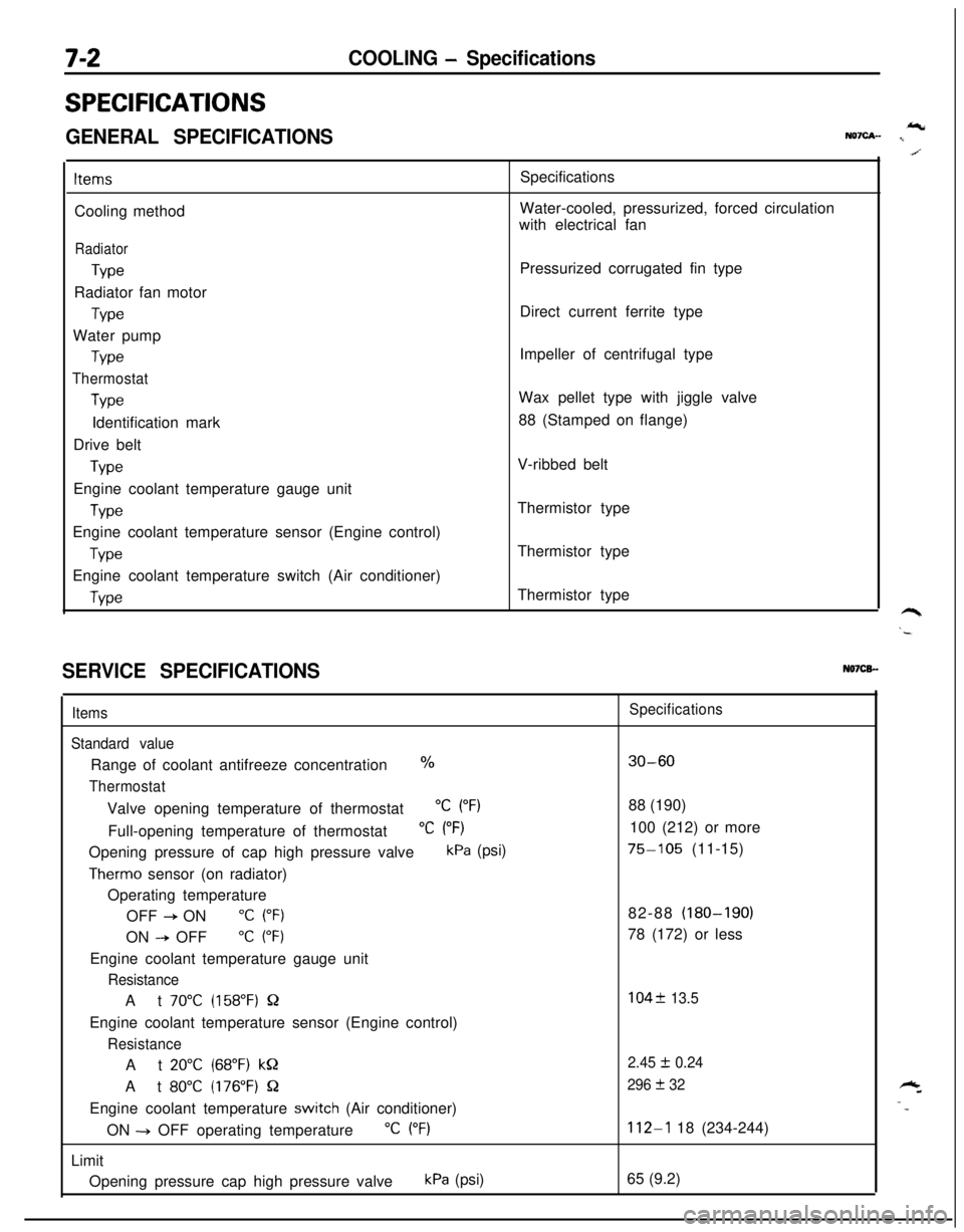
7-2COOLING - Specifications
SPECIFICATIONS
GENERAL SPECIFICATIONSIcNQ7cA- I
ItemsCooling method
Radiator
TypeRadiator fan motor
TypeWater pump
Type
Thermostat
TypeIdentification mark
Drive belt
TypeEngine coolant temperature gauge unit
WeEngine coolant temperature sensor (Engine control)
TypeEngine coolant temperature switch (Air conditioner)
WeSpecifications
Water-cooled, pressurized, forced circulation
with electrical fan
Pressurized corrugated fin type
Direct current ferrite type
Impeller of centrifugal type
Wax pellet type with jiggle valve
88 (Stamped on flange)
V-ribbed belt
Thermistor type
Thermistor type
Thermistor type
SERVICE SPECIFICATIONSN07CB.-
Items
Standard valueRange of coolant antifreeze concentration
%
ThermostatValve opening temperature of thermostat
“C (“F)Full-opening temperature of thermostat
“C (“F)Opening pressure of cap high pressure valve
kPa (psi)
Therm0 sensor (on radiator)
Operating temperature
OFF
+ ON“C (“F)ON
--P OFF“C (“F)Engine coolant temperature gauge unit
ResistanceAt
70°C (158°F) QEngine coolant temperature sensor (Engine control)
ResistanceAt
20°C (68°F) kQAt
80°C (176°F) QEngine coolant temperature
switch (Air conditioner)
ON -+ OFF operating temperature
“C (“F)Limit
Opening pressure cap high pressure valve
kPa (psi)
Specifications
30-6088 (190)
100 (212) or more
75-105 (11-15)
82-88 (180-190)
78 (172) or less
104f 13.5
2.45
I!I 0.24
296
+ 32
112-l 18 (234-244)
65 (9.2)
Page 251 of 1216

COOLING - Specifications7-3
TORQUE SPECIFICATIONSN07CG.
ItemsRadiator insulator
upperThermosensor to radiator
Automatic transaxle oil cooler hose cramp
Automatic transaxle oil cooler hose mounting bolt
Water outlet fitting bolts
Engine mount insulator nut (large)
Engine mount insulator nut (small)
Engine mount bracket to engine
Bracket between engine mount bracket and engine
Tension pulley bracket for air conditioner
<1.8L Engine>
Water pump installation bolt
Bolt head mark “4T”
Bolt head mark “7T”
Water pulley bolt
pumpDamper pulley, crankshaft pulley
<1.8L Engine>
<2.0L DOHC Engine>
Timing belt front upper cover installation bolt
Timing belt front lower cover installation bolt
Crankshaft sprocket installation bolt
Timing belt
B tensioner
Tension pulley bracket for air conditioner
<2.0L DOHC Engine>
Automatic tensioner installation bolt
Tensioner pulley installation bolt
Oil level
gaugeFront exhaust pipe to exhaust manifold
Exhaust manifold cover (A)
Flange bolt: 8
x 12 mm (.31 x .47 in.)
Washer assembled bolt: 6
x 14 mm (.24x.55in.)
<2.0L DOHC Engine (Non-Turbo)>
Exhaust manifold cover
(8)
Heat protecter (A)
Heat protecter
(B)
Exhaust manifold to cylinder head<1.8L Engine>
<2.0L DOHC Engine>
Engine hanger to engine bracket
JVater inlet pipe installation bolt
Transaxle side
Engine block side
<1.8L Engine>
<2.0L DOHC Engine>
'ower steering oil pump to oil pump bracket
‘ower steering oil pump bracket to engine
Nmft.lbs.
9-14
7-103-4
2-3
4-63-4
3-52-4
17-2012-14
60-8043-58
30-4022-29
50-6536-47
17-2612-19
18-2213-15
12-15
9-11
20-2714-20
8-106-7
15-18
11-13
20-3014-22
IO-127-9
10-127-9
110-13080-9415-22
11-16
23-27
17-20
20-2714-2043-55
31-4012-15
9-11
30-4022-29
40-6029-43
30-4022-29
27-33
20-24
8-106-7
12-15
9-11
12-15
9-11
12-15
9-11
12-15
9-l 1
15-2011-14
25-3018-22
12-15
9-11
43-55
31-40
IO-127-9
12-15
9-11
35-4525-33
25-3318-24
Page 252 of 1216

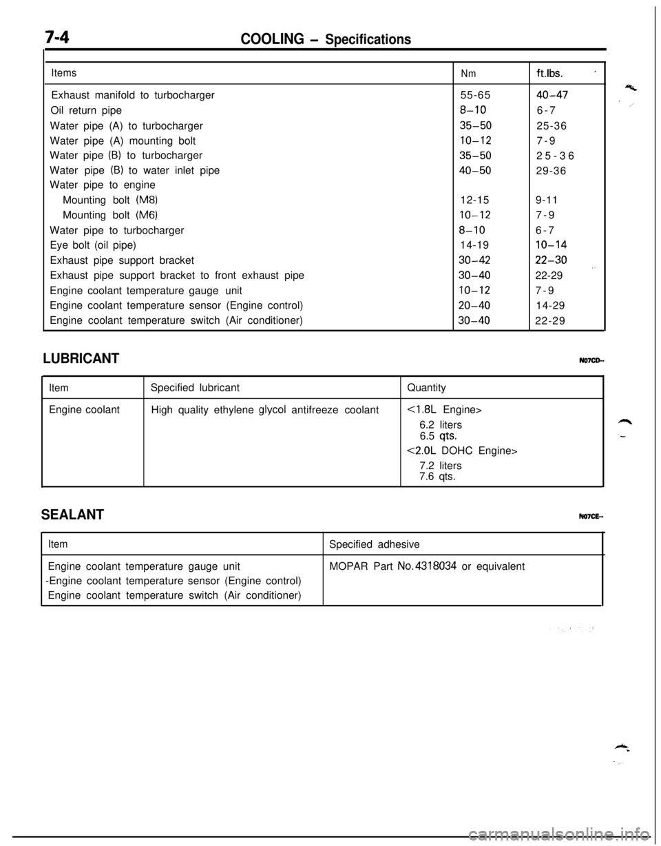
7-4COOLING - Specifications
ItemsExhaust manifold to turbocharger
Oil return pipe
Water pipe (A) to turbocharger
Water pipe (A) mounting bolt
Water pipe
(B) to turbocharger
Water pipe
(B) to water inlet pipe
Water pipe to engine
Mounting bolt
(M8)Mounting bolt
(M6)Water pipe to turbocharger
Eye bolt (oil pipe)
Exhaust pipe support bracket
Exhaust pipe support bracket to front exhaust pipe
Engine coolant temperature gaugeunit
Engine coolant temperature sensor (Engine control)
Engine coolant temperature switch (Air conditioner)
Nmft.lbs. _155-65
40-47
8-106-7
35-5025-36
10-127-9
35-5025-36
40-5029-36
12-159-11
10-127-9
8-106-7
14-19
10-14
30-4222-30
30-4022-29 .’
10-127-9
20-4014-29
30-4022-29
LUBRICANT
ItemEngine coolantSpecified lubricant
High quality ethylene
glycol antifreeze coolantQuantity
6.2 liters
6.5
qts.
<2.0L DOHC Engine>
7.2 liters
7.6 qts.
SEALANTNO7CE-.
ItemEngine coolant temperature gauge unit
-Engine coolant temperature sensor (Engine control)
Engine coolant temperature switch (Air conditioner)Specified adhesive
MOPAR Part No.4318034 or equivalent
Page 255 of 1216

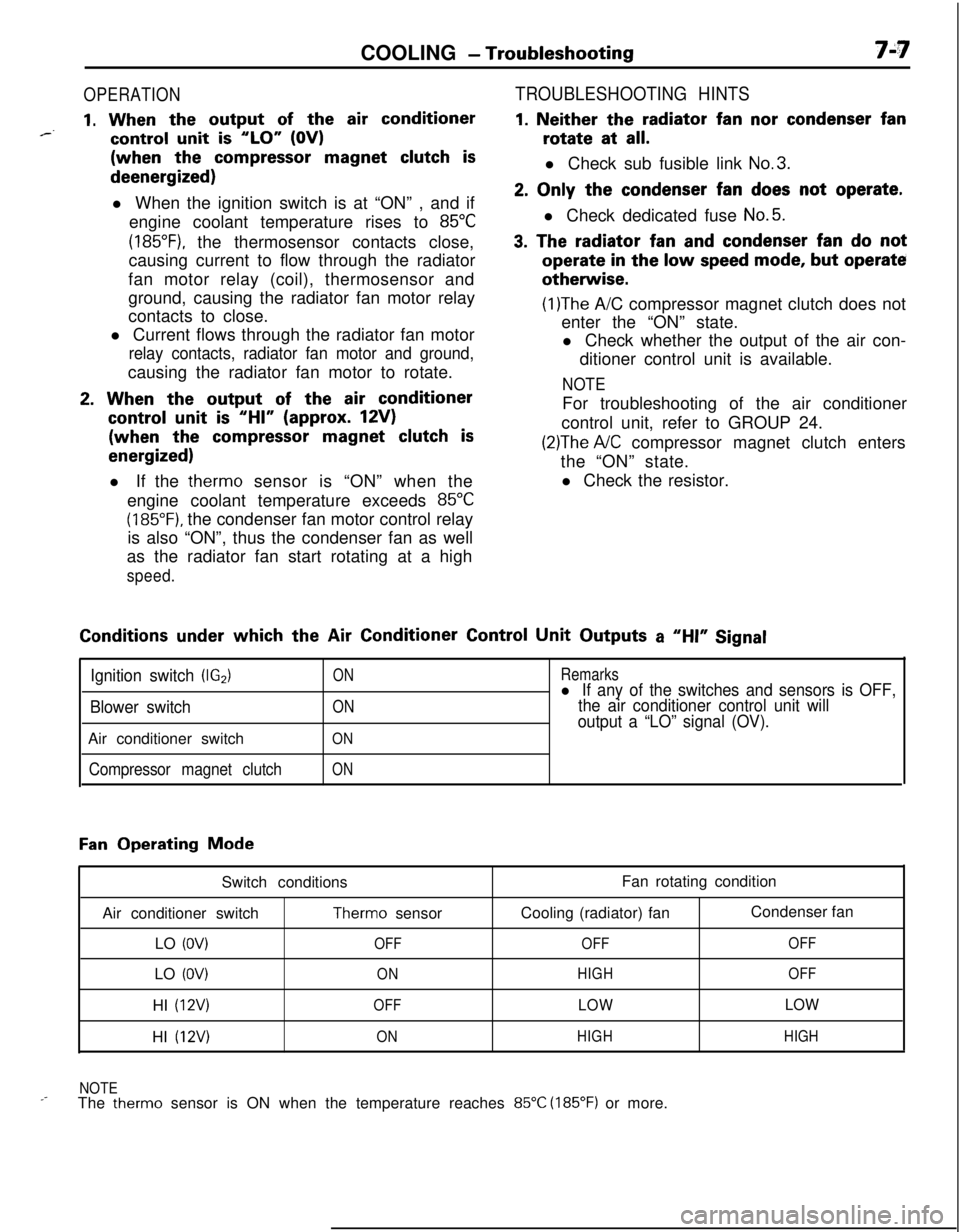
COOLING - Troubleshooting7A7
OPERATION
1. When the output of the air conditioner*--control unit is “LO” (OV)(when the
compressor magnet clutch isdeenergized)
l When the ignition switch is at “ON” , and if
engine coolant temperature rises to
85°C
(185”F), the thermosensor contacts close,
causing current to flow through the radiator
fan motor relay (coil), thermosensor and
ground, causing the radiator fan motor relay
contacts to close.
l Current flows through the radiator fan motor
relay contacts, radiator fan motor and ground,causing the radiator fan motor to rotate.
2. When the output of the air conditioner
control unit is “HI” (approx. 12V)(when the
compressor magnet clutch is
energized)l If the therm0 sensor is “ON” when the
engine coolant temperature exceeds
85°C
(185°F). the condenser fan motor control relay
is also “ON”, thus the condenser fan as well
as the radiator fan start rotating at a high
speed.
TROUBLESHOOTING HINTS
1. Neither the radiator fan nor condenser fanrotate at
all.l Check sub fusible link
No.3.
2. Only the condenser fan does not operate.l Check dedicated fuse
No.5.
3. The radiator fan and condenser fan do notoperate
in the low speed mode, but operateotherwise.
(1)The A/C compressor magnet clutch does not
enter the “ON” state.
l Check whether the output of the air con-
ditioner control unit is available.
NOTEFor troubleshooting of the air conditioner
control unit, refer to GROUP 24.
(2)The A/C compressor magnet clutch enters
the “ON” state.
l Check the resistor.Conditions
under which the Air Conditioner Control Unit Outputs a “HI” Signal
Ignition switch (IG2)
Blower switchAir conditioner switch
Compressor magnet clutch
ON
ON
ON
ON
Remarksl If any of the switches and sensors is OFF,
the air conditioner control unit will
output a “LO” signal (OV).
Fan Operating Mode
Switch conditions
Air conditioner switch
Therm0 sensor
LO
(OV)OFFLO
(OV)ONHI
(12V)OFFHI
(12V)ONFan rotating condition
Cooling (radiator) fanCondenser fan
OFFOFF
HIGHOFF
LOWLOW
HIGHHIGH
NOTE
_-The therm0 sensor is ON when the temperature reaches 85°C (185°F) or more.
Page 260 of 1216

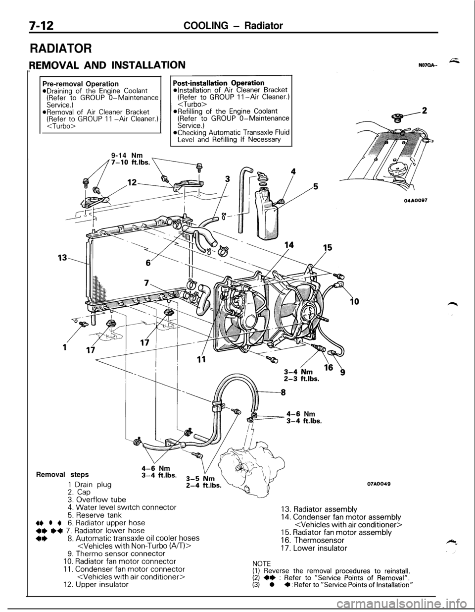
7-12COOLING - Radiator
RADIATORPre-removal Operation
@Draining of the Engine Coolant(Refer to GROUP O-Maintenance(Refer to GROUP II-Air Cleaner.)
Service.)
I I
9-14 Nm
_
4-6 Nm3-4 ft.lbs.Removal steps
1 Drain plug2. Cap3. Overflow tube.
4-9 Nm3-4 ft.lbs.
4. Water level switch connector
5. Reserve tank~~ l +6. Radiator upper hose
+e e+ 7. Radiator lower hose
*I)8. Automatic transaxle oil cooler hoses
11. Condenser fan motor connector
04AOOS7
07A0049
13. Radiator assembly14. Condenser fan motor assembly
16. Thermosensor
17. Lower insulator
NOTE(1) Reverse the removal procedures to reinstall.(2) +e : Refer to “Service Points of Removal”.(3) l + : Refer to “Service Points of Installation”