Page 1175 of 1216
HEATERS AND AIR CONDITIONING - Heater Unit24-31
HEATER UNIT
REMOVAL AND INSTALLATIONN24m-
Pre-removal OperationeDraining of Engine Coolant(Refer to GROUP 7-Service Adjust-ment Procedures.)
@Removal of Floor Console and In-
strument Panel
(Refer to GROUP 23-Floor Consoleand Instrument Panel.)Post-installation Operation
*Supplying of Coolant
(Refer to GROUP 7-Service Adjust-ment Procedures.)
l installation of Floor Console and
Instrument Panel
(Refer to GROUP 23-Floor Consoleand Instrument Panel.)
shower duct>
Jshower duct>
Removal steps
1. Center reinforcement
2. Shower duct (R.H.)
3. Distribution foot duct
;: ;Z;;er duct assembly
:z6. Evaporator
7. Heater unit
8. Lap cooler duct (A)
NOTE(1) Reverse the removal procedures to reinstall.(2) 4* : Refer to “Service Points of Removal”.
Page 1176 of 1216
24-32HEATERS AND AIR CONDITIONING - Heater Unit
SERVICE POINTS OF REMOVAL6. REMOVAL OF
EVAPORATERRefer to GROUP 24-34.
NMISAO
20A04177. REMOVAL OF HEATER UNIT
NOTEIn order to prevent bolts from falling into the blower
assembly, set the inside/outside air-selection damper to
the position that permits outside air introduction.
INSPECTIONN24lcAal Check the operation of dampers and link mechanism.
l Check the heater core for clogging and water leakage.
HEATER CORE REPLACEMENT
(1) Remove the heater unit.
(2) Remove the plate.N24lDAH
(3) Pull out the heater core from the heater unit.
(4) Insert the heater core into the heater unit.
NOTEThis work must be done carefully so as not to damage the
fin part or the pad part.
(5)
Install the plate.
(6) Install the heater unit.
Page 1178 of 1216

24-34HEATERS AND AIR CONDITIONING - Evaporator
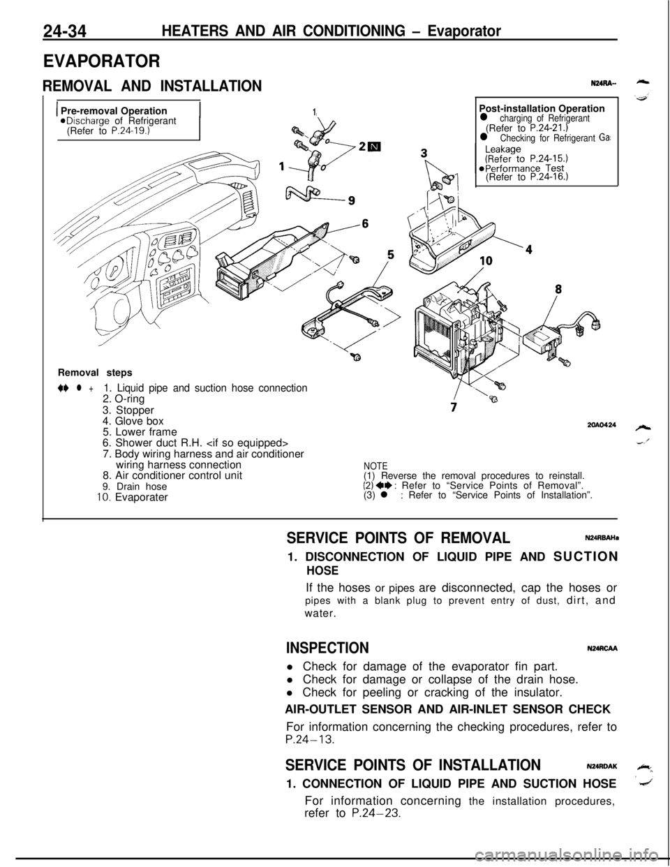
EVAPORATOR
REMOVAL AND INSTALLATION
1 Pre-removal Operation1aDischarge of Refrigerant
(Refer to P.24.19.)Post-installation Operation
l charging of Refrigerant(Refer to P.24-21.)l Checking for Refrigerant Ga:(Refer to
P.24-16.)Removal steps
N l +1. Liquid pipe and suction hose connection2. O-ring
3. Stopper
4. Glove box
5. Lower frame
6. Shower duct R.H.
7. Body wiring harness and air conditioner
wiring harness connection
8. Air conditioner control unit
9. Drain hose
10. Evaporater
2OAO424
NOTE(1) Reverse the removal procedures to reinstall.
(2) ++ : Refer to “Service Points of Removal”.
(3) l : Refer to “Service Points of Installation”.
SERVICE POINTS OF REMOVALN24RBAHa1. DISCONNECTION OF LIQUID PIPE AND SUCTION
HOSEIf the hoses or pipes are disconnected, cap the hoses or
pipes with a blank plug to prevent entry of dust, dirt, and
water.
INSPECTIONN24RCAAl Check for damage of the evaporator fin part.
l Check for damage or collapse of the drain hose.
l Check for peeling or cracking of the insulator.
AIR-OUTLET SENSOR AND AIR-INLET SENSOR CHECK
For information concerning the checking procedures, refer to
P.24-13.
SERVICE POINTS OF INSTALLATIONN24RDAK1. CONNECTION OF LIQUID PIPE AND SUCTION HOSE
For information concerning the installation procedures,
refer to
P.24-23.
Page 1179 of 1216
HEATERS AND AIR CONDITIONING - Evaporator
DISASSEMBLY AND REASSEMBLY
24-35
NURE--
3ZOAO457Disassembly steps
1. Wiring harness2. Air conditioner control unit
4*3. Clips4. Evaporater case (upper)5. Air inlet sensor
6. Air therm0 sensor
7. Evaporater case (lower)
8. Evaporater assembly9. Grommet
IO. Insulator11. Rubber insulator
12. Clip+) ++ 13. Expansion valve14. O-ringNOTE
(1) Reverse the disassembly procedures to reassyyble(2) ~~ : Refer to “Service Points of Disassembly,(3) +4 : Refer to“Service Points of Reassembly
(4) m : Non-reusable parts.
.
Page 1197 of 1216

.^
EMISSION CONTROL
SYSTEMS
CONTENTSN25AA-
CATALYTICCONVERTER...............................20CRANKCASE EMISSION CONTROL
SYSTEM...........................................................7Components Location
...................................7Crankcase Ventilation System
Inspection......................................................8Positive Crankcase Ventilation Valve
...........8EVAPORATIVE EMISSION CONTROL
SYSTEM...........................................................9
AirConditionerSwitch.................................14Air Flow Sensor, Engine Coolant
Temperature Sensor and Intake Air
Temperature Sensor
.....................................14
Canister.........................................................14Components Location
...................................9
FuelFillerCapInspection............................14Overfill Limiter (Two-way Valve)
..................14
PurgeControlSolenoidValve......................13Purge Control
SystemInspection................11
PurgeControlValve.....................13EXHAUST GAS RECIRCULATION (EGR)
SYSTEM...........................................................15Air-fuel Ratio Control (MPI) System
............20Components Location
...................................15EGR Control Solenoid Valve
.................................................19
EGR
SystemInspection...............................17EGR Temperature Sensor
......19
EGR Valve.....................................................18
Therm0 Valve
2.0L DOHC Engine>...................................18
SPECIFICATIONS.............................................2General Specifications
..................................2
Sealant..........................................................2Service Specifications
...................................2
TorqueSpecifications...................................2
TROUBLESHOOTING......................................3
VACUUMHOSES...........................................4
VacuumHosesRouting...............................4
Page 1210 of 1216
25-14EMISSION CONTROL SYSTEMS- Evaporative Emission Control System
(5) Measure the resistance between the terminals of the
solenoid valve.
Standard value: 36-44
Q [at 20°C (68OF)]_
6EM137
AIR FLOW SENSOR, ENGINE COOLANT TEMPER-
ATURE SENSOR AND INTAKE AIR TEMPERA-
TURE SENSORTo inspect these parts, refer to GROUP
14-MPI System
Components.‘.
AIR CONDITIONER SWITCHTo inspect the air conditioner switch, refer to GROUP
24’--AirConditioner Switch.
OVERFILL LIMITER (TWO-WAY VALVE)N2BlBE&To inspect the overfill limiter (two-way valve), refer to GROUP
14-Fuel Tank.
CANISTERNzslBmTo inspect the canister, refer to GROUP
14-Fuel Line and
Vapor Line.
FUEL FILLER CAP INSPECTIONNZSIBJACheck the gasket of the fuel filler cap, and, the filler cap itself,
for damage or deformation; replace the cap if necessary.