Page 1 of 1216

BACKUPGROUP INDEX &ma
;r Service Manual
LASER
TALON
1991
Volume-l
Engine, Chassis
& Body
FOREWORDThis Service Manual has been prepared with the
latest service information available at the time of
‘* publication.It is subdivided into various group
categories and each section contains diagnosis,
disassembly, repair, and installation procedures
along with complete specifications and tightening
references. Use of this manual will aid in properly
performing any servicing necessary to maintain or
restore the high levels of performance and reliabilitydesigned into these outstanding vehicles.
This BACKUP DSM manual IS to be used ONLY as a BACKUP. Please DO NOT REDISTRIBUTEWHOLE SECTIONS. This BACKUP was sold to you under the fact that you do indeed OWNa GENUINE DSM MANUAL. It CANNOT BE considered a REPLACEMENT (Unless your originalmanual was lost or destroyed.)Please See
README.N or README.HTML for additional information
Thank you. G~mm~emymanual@hotma~l.com
1,
wA
CHRYSLER
CORPORATION
Chrysler Corporation reserves the right to make changes in design 0’: tomake additions to or improvements in its products without lmqoslngd ., . any obligations upon itself to install them on its products previouslymanufactured.
0 1990 Mitsubishi Motors CorporationPrinted in U.S.A.Introduction and
Master
Troubleshooting. . . . . .,. . . . . . . . . r...m,
Lubrication and Maintenance . . . . . . . . ‘-0‘8
; “. i,
.Front Suspension. . . . . . . . . . . . . . ..*............d...Rear Axle
. . . . . . . . . . . . . . . . . . . . . . . . . . . . ..‘.....................
/
ServiceBrakes-Parking. . . . . . . . . . . . . . . . . . . . . . . . . . . . . . . . . . . . . .
Clutch. . . . . . . . . . . . . . . . . . . . . . . . . . . . . . . . . ..~......................‘t.
Cooling. . . . . . . . . . . . . . . . . ..i....................................
,., .‘,-,
Engine..i....~....r...............~....~.*,.~.~.~,‘~~...;..~~..Intake and Exhaust
. . . . . . ..L....................Fuel System
. . . . . . . . . . . ..ti.......r................~...Propeller Shaft
.......................................IRear
Suspensiori.............................y.f...
ManualSteering- Power.....................................Manual
I
transaxle-Automatic .............:;i...,;.....;Wheels
and Tires.................................
Body.............................................................Heater & Air Conditioning
..............Emission
Contr6l Systems..............
INOTE: For Electrical, refer toVolume-2 “Electrical”.
Page 39 of 1216

LUBRICATION AND MAINTENANCE - Recommended Lubrie’ntsand Lubrtcant Capacttles Table
LUBRICANT CAPACITIES TABLE
Description
Engine Oil Engine Oil
Crankcase (including oil filter) Crankcase (including oil filter)
<1.8L Engine><1.8L Engine><2.0L DOHC Engine><2.0L DOHC Enaine>Oil filter Oil filter
Oil cooler (Turbo) Oil cooler (Turbo)
Metric measureU.S. measure
3.9 liters’.4.4 liters
0.4 liter
0.3 liter
4.‘1 qts.4.6 qts.
‘h qt.Y2 qt.
Cooling System (including heater and coolant reserve system)
<2.0L DOHC Engine>6.2 liters
7.2 liters6.6
qts.
7.6 qts.
Manual Transaxle
1.8liters1.9qts.2.2liters2.3qts.
2.3liters
2.4qts.
Transfer
I0.6 literI.63 qt.
Au:oFmqaAtF2pnsaxle
Rear Axle
Power Steering
Fuel Tank
"C“F4912040
104
27
80
1660
1050
032-10
14-15
5-20-4
-23-10
-29-20
6.1 liters6.4 qts.
7.0 liters7.4 qts.
0.7 liter.74 qt.
0.9 liter.95 sf.60 liters
15.9 gal?.
’ ~ “.SELECTION OF LUBRICANTS
ENGINE OIL
Engine oil should be used which conform to the requirements
of the API classification “For Service SG” or “For Service
SGKD”, and have the proper SAE grade number for the
expected temperature range.
Caution
Nondetergent or straight mineral oil must never be used.
Energy Conserving Oil
In order to improve fuel economy and conserve energy new,
lower friction engine oils have been developed. These oils are
readily available and can be identified by such labels as “EnergyConserving”,“Energy Saving”,“Improved Fuel Economy”,
etc.
/”SAE
5W-20 Not recommended for sustained
high speed vehicle operation.**SAE
5W-30 may be used for operation in very
cold weather areas where the lowest atmos-
pheric temperature is below
-23°C (-10°F).
Page 548 of 1216

14-94FUEL SYSTEM - Fuel Tank
Outlet side_ Inlet side01
W838
Positioning projection
03A0220SERVICE POINTS OF REMOVALtilirro8AH
6. DISCONNECTION OF HIGH PRESSURE FUEL
H;OSECaution
Cover the hose connection with rags to prevent splash
of fuel that could be caused by some residual pressure
in the fuel pipe line.
INSPECTIONN14GCAll Check the hoses and the pipes for crack or damage.
l Check the fuel tank cap for malfunction.
l Check the fuel tank for deformation, corrosion or crack.
0,. Check the fuel tank for dust or foreign material.
NOTE
If the inside of the fuel tank is to be cleaned, use any one ofthe following:
(1) Kerosene
(2)
Trichloroethylene-(3) A neutral emulsion type detergent
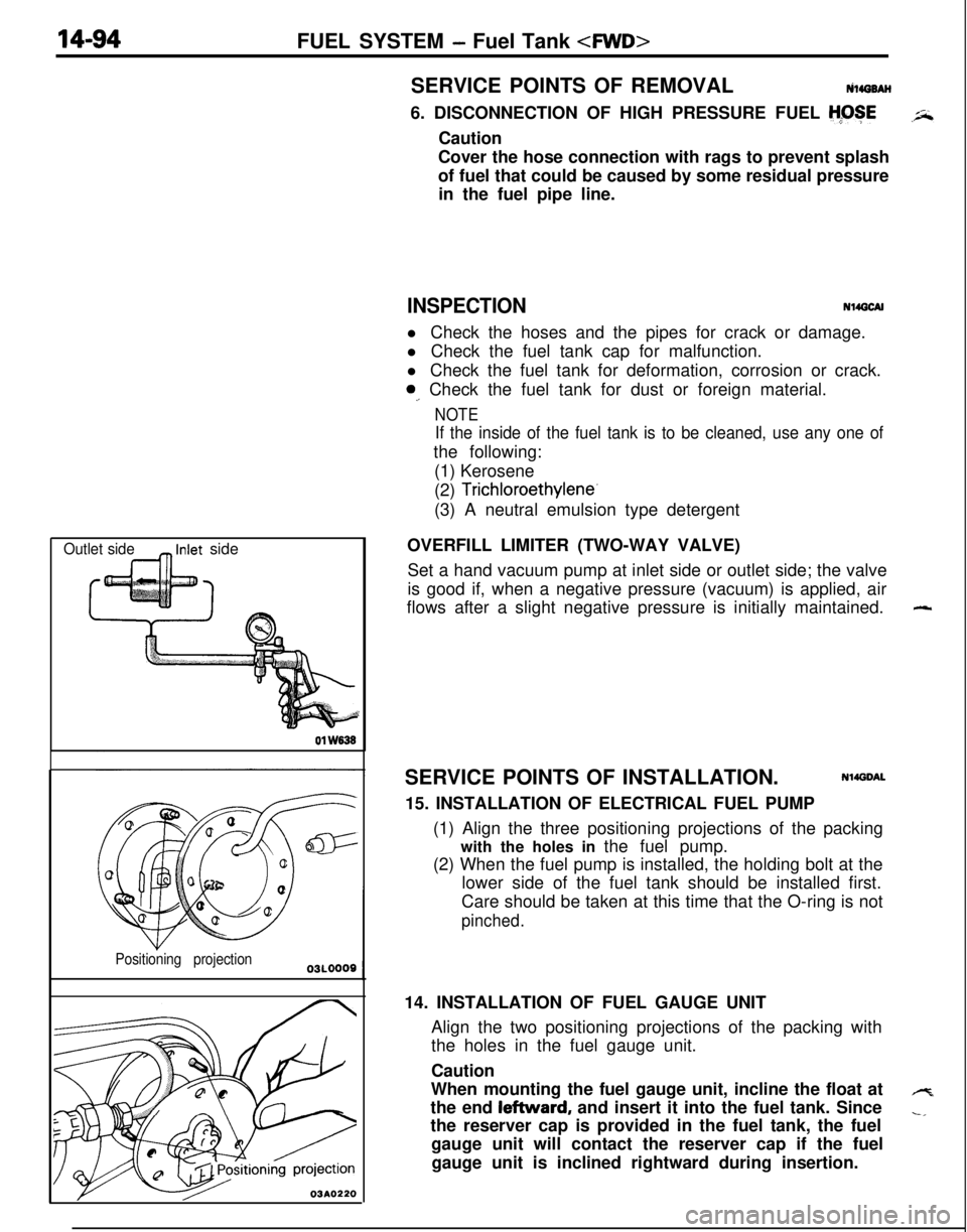
OVERFILL LIMITER (TWO-WAY VALVE)
Set a hand vacuum pump at inlet side or outlet side; the valve
is good if, when a negative pressure (vacuum) is applied, air
flows after a slight negative pressure is initially maintained.
SERVICE POINTS OF INSTALLATION.
Nl4DDAL15. INSTALLATION OF ELECTRICAL FUEL PUMP
(1) Align the three positioning projections of the packing
with the holes in the fuel pump.
(2) When the fuel pump is installed, the holding bolt at the
lower side of the fuel tank should be installed first.
Care should be taken at this time that the O-ring is not
pinched.14. INSTALLATION OF FUEL GAUGE UNIT
Align the two positioning projections of the packing with
the holes in the fuel gauge unit.
Caution
When mounting the fuel gauge unit, incline the float at
the end leftward, and insert it into the fuel tank. Since
the reserver cap is provided in the fuel tank, the fuel
gauge unit will contact the reserver cap if the fuel
gauge unit is inclined rightward during insertion.
-
4
-,