Page 1049 of 1216
BODY - Specifications/Special Tools23-5
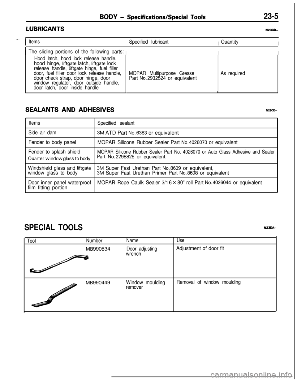
LUBRICANTSNZXD-
.^
IItemsSpecified lubricantIQuantityI
IThe sliding portions of the following parts:III
Hood latch, hood lock release handle,
hood hinge, liftgate latch, liftgate lock
release handle, liftgate hinge, fuel filler
door, fuel filler door lock release handle,
door check strap, door hinge, doorwindow regulator, door outside handle,
door latch, door inside handle
SEALANTS AND ADHESIVES
MOPAR Multipurpose Grease
Part No.2932524 or equivalent
As required
ItemsSpecified sealant
Side air dam
3M ATD Part No.6383 or equivalent
Fender to body panel
MOPAR Silicone Rubber Sealer Part No.4026070 or equivalent
Fender to splash shield
MOPAR Silicone Rubber Sealer Part No. 4026070 or Auto Glass Adhesive and Sealer
Quarter window glass to bodyh-t No.2298825 Or equivalent
Windshield glass and liftgate3M Super Fast Urethan Part No.8609 or equivalent,
window glass to body3M Super Fast Urethan Primer Part No.8608 or equivalent
Door inner panel waterproofMOPAR Rope Caulk Sealer
3/l 6 x 80” roll Part No.4026044 or equivalent
film fitting portion
SPECIAL TOOLS
ToolNumber
MB990834
Name
Door adjusting
wrench
Use
Adjustment of door fit
MB990449Window moulding
removerRemoval of window moulding
Page 1050 of 1216
BODY - Troubleshooting
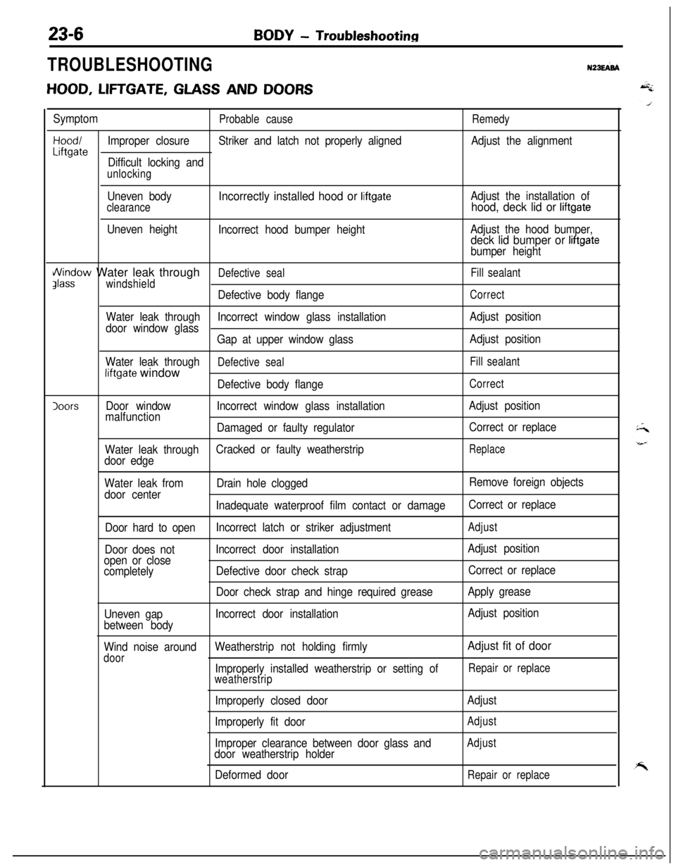
TROUBLESHOOTINGN23EFd
HOOD, LIFTGATE, GLASS AND DOORS
SymptomProbable causeRemedy
Hood/Improper closureStriker and latch not properly alignedAdjust the alignmentLiftgateDifficult locking and
unlocking
Uneven body
clearance
Uneven height
Incorrectly installed hood or liftgate
Incorrect hood bumper heightAdjust the installation of
hood, deck lid or liftgate
Adjust the hood bumper,deck lid bumper or liftgate
bumper height
i/\/indow Water leak throughDefective sealFill sealantJlasswindshield
Defective body flangeCorrect
Water leak throughIncorrect window glass installationAdjust position
door window glass
Gap at upper window glassAdjust position
Water leak through
Defective sealFill sealantliftgate window
Defective body flangeCorrect
IoorsDoor windowIncorrect window glass installationAdjust position
malfunction
Damaged or faulty regulatorCorrect or replace
Water leak throughCracked or faulty weatherstrip
Replace
door edge
Water leak fromDrain hole cloggedRemove foreign objects
door center
Inadequate waterproof film contact or damageCorrect or replace
Door hard to openIncorrect latch or striker adjustment
Adjust
Door does notIncorrect door installationAdjust position
open or close
completelyDefective door check strapCorrect or replace
Door check strap and hinge required greaseApply grease
Uneven gapIncorrect door installationAdjust position
between body
Wind noise aroundWeatherstrip not holding firmly
Adjust fit of door
doorImproperly installed weatherstrip or setting ofRepair or replace
weatherstrip
Improperly closed door
Improperly fit door
Improper clearance between door glass and
door weatherstrip holder
Deformed doorAdjust
Adjust
Adjust
Repair or replace
Page 1054 of 1216
23-10BODY - Troubleshooting
(PABBENGER’B BIDE)v 1
E-51
‘S
E-05
I2
m3458
POWER WINDOW
MOTOR
E-04
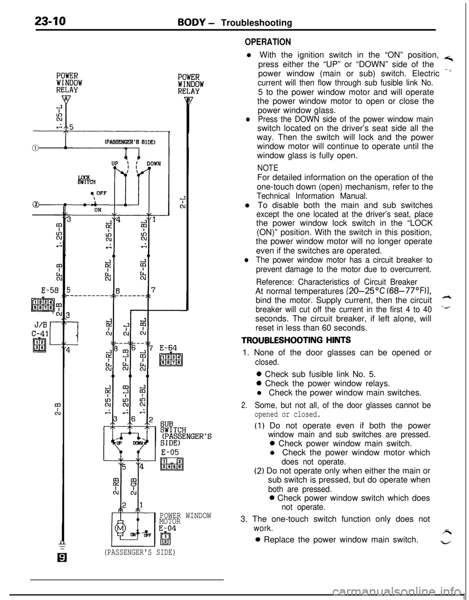
OPERATIONl With the ignition switch in the “ON” position,
rs;,press either the “UP” or “DOWN” side of the
power window (main or sub) switch. Electric
-*
current will then flow through sub fusible link No.5 to the power window motor and will operate
the power window motor to open or close the
power window glass.
lPress the DOWN side of the power window mainswitch located on the driver’s seat side all the
way. Then the switch will lock and the power
window motor will continue to operate until the
window glass is fully open.
NOTEFor detailed information on the operation of the
one-touch down (open) mechanism, refer to the
Technical Information Manual.l To disable both the main and sub switches
except the one located at the driver’s seat, placethe power window lock switch in the “LOCK
(ON)” position. With the switch in this position,
the power window motor will no longer operate
even if the switches are operated.
lThe power window motor has a circuit breaker to
prevent damage to the motor due to overcurrent.
Reference: Characteristics of Circuit BreakerAt normal temperatures
[ZO-25OC (68-77”F)I,bind the motor. Supply current, then the circuit
h
breaker will cut off the current in the first 4 to 40\&’seconds. The circuit breaker, if left alone, will
reset in less than 60 seconds.
TROUBLESHOOTING HINTS1. None of the door glasses can be opened or
closed.0 Check sub fusible link No. 5.0 Check the power window relays.
l Check the power window main switches.
2.Some, but not all, of the door glasses cannot be
opened or closed.
(I) Do not operate even if both the power
window main and sub switches are pressed.0 Check power window main switch.
l Check the power window motor which
does not operate.
(2) Do not operate only when either the main or
sub switch is pressed, but do operate when
both are pressed.0 Check power window switch which does
not operate.3. The one-touch switch function only does not
work.A0 Replace the power window main switch.
w
(PASSENGER'S SIDE)
Page 1055 of 1216
BODY - Troubleshooting234'1
CENTRAL DOOR LOCKING SYSTEM N23EBFF
CIRCUIT DIAGRAM..-
,-.
SUB FU0IBLELINK 8
g
J/Bk 1 c-47 'B
@
L
10A
L
is411
J/B
L
4c
c-51
c-49
12
al34
3 E-64
DOOR LOCKE-49DOOR LOCKE-09
KX3b-AC-WIOB-Xi:
Page 1056 of 1216
2342BODY - Troubleshooting
CENTRAL DOOR LOCKING SYSTEM
CIRCUIT DIAGRAM
IGNITISW1 TCH
c
c-54 c
ONIGI(ACC) SW-
r'334
9P------.IX
0
10A
\/------.1
43bC-52-:
THEFT-ALARMg$;ROL $jr------51z------.
I
CH(IG1)
7
431OA
1
fl
fiie;yLOCK
c-34x
f!iiGqII
?
$4m5--- -----1!2---w---w---: (II
IL-++;I
II
j2s9
L--------------- _
C-20 5~7f.f5,8m~ii-~,i;----'
I1
3 E-50
3 E-64
1
1
X95-AC-Ull00-NC
DOOR LOCKE-09%%8°iIDE,
m
DOOR LOCKE-49
ACTUATOR
Page 1057 of 1216

BODY - Troubleshooting23-13
OPERATION
TROUBLESHOOTING HINTS
-.l If the inside lock knobs of the doors are placedin the LOCK (or UNLOCK) position, the switch inthe door lock actuator will be “OFF” (or “ON”),
and the output transistor will be “ON” for 0.5
second according to the timer function in the
door lock control unit (or theft-alarm control unit).As a result, the LOCK side (or UNLOCK side) of
the door lock relay will be “ON”, operating the
actuators of all of the doors.
NOTE
The door lock actuator contains a PTC thermistor
to prevent damage caused by overheating of the
motor. If the central door lock is frequently used,the actuator may temporarily fail to operate. If it
returns to normal in a few minutes, it is not
defective.
1.
2.One of the door lock actuators fails to operate.
l Check the door actuator which fails to
operate.Cannot be placed in the LOCK or UNLOCK
position by the inside lock knob on either driver’s
or front passenger’s seat side.0 Check the switch in the actuator.0 Check the door lock control unit (or
theft-alarm control unit).
DOOR LOCK CONTROL UNIT (OR THEFT-ALARM CONTROL UNIT) TERMINAL VOLTAGE (Connector
Connected)
TerminalSignal nameConditionTerminalNo.voltage1 or
5”’Door lock relayThe moment the inside lock knob is0.5 vs2
activation signal
pressed down (approx. 0.5 sec.)
NormallySystem voltage2 or 19”’
(Driver’s seat side) insideWhen the inside lock knob is placedSystem voltage
door lock knob signalin the “LOCK” position
When the inside lock knob is placedov
in the “UNLOCK” position3 or
4”’Door lock relayThe moment the inside lock knob is0.5 v2
activation signalpulled up (approx. 0.5 sec.)
NormallySystem voltage4 or 20”’
(Passenger’s seat side)When the inside lock knob is placedSystem voltage
inside door lock knob signalin the “LOCK” position
When the inside lock knob is placedovin the “UNLOCK” position5 or
12*’Power supplyAlwaysSystem voltage6 or
7(11)*’GroundAlwaysov
NOTE*I: Vehicles with theft-alarm system.
*2:Because of the internal resistance of the output transistor, the normal terminal voltage is 0.5 V. If it is 0 V, an open orshort circuit in the harness is suspected.
Page 1063 of 1216
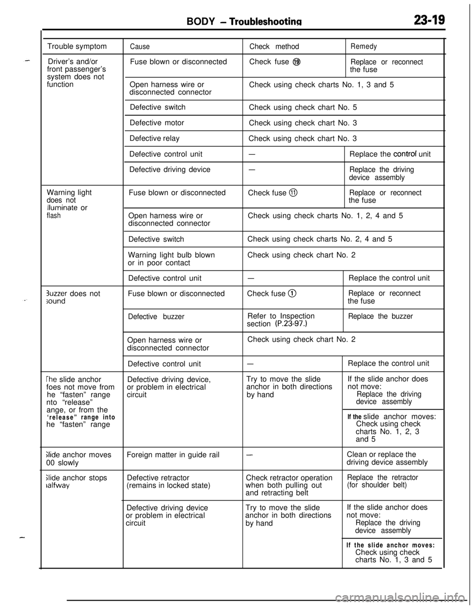
BODY - Troubleshootinn2349Trouble symptom
Driver’s and/or
front passenger’s
system does not
function
CauseFuse blown or disconnected
Open harness wire or
disconnected connectorCheck methodRemedyCheck fuse
@IReplace or reconnectthe fuse
Check using check charts No. 1, 3 and 5
Defective switch
Defective motor
Defective relay
Defective control unit
Defective driving deviceCheck using check chart No. 5
Check using check chart No. 3
Check using check chart No. 3
-Replace the control unit
-Replace the driving
device assemblyWarning light
does notlluminate or
flashFuse blown or disconnected
Open harness wire or
disconnected connectorCheck fuse
@IReplace or reconnectthe fuse
Check using check charts No. 1, 2, 4 and 5
Defective switch
Warning light bulb blown
or in poor contactCheck using check charts No. 2, 4 and 5
Check using check chart No. 2
3uzzer does notsoundDefective control unit
Fuse blown or disconnected
Defective buzzer
-Check fuse @
Refer to Inspection
section
(P.23-97.)Replace the control unit
Replace or reconnectthe fuse
Replace the buzzerOpen harness wire or
disconnected connectorCheck using check chart No. 2
Defective control unit
-Replace the control unit
The slide anchorDefective driving device,Try to move the slideIf the slide anchor does
foes not move fromor problem in electricalanchor in both directionsnot move:
he “fasten” rangecircuitby hand
Replace the drivingnto “release”device assemblyange, or from the
‘release”range intoIf the slide anchor moves:
he “fasten” rangeCheck using check
charts No. 1, 2, 3
and 5
Glide anchor moves
00 slowly
Slide anchor stopsralfwayForeign matter in guide rail
Defective retractor
(remains in locked state)
-Clean or replace the
driving device assembly
Check retractor operation
Replace the retractorwhen both pulling out(for shoulder belt)and retracting belt
Defective driving deviceTry to move the slide
or problem in electricalanchor in both directions
circuit
by handIf the slide anchor does
not move:
Replace the driving
device assemblyIf the slide anchor moves:
Check using check
charts No. 1, 3 and 5
Page 1064 of 1216
23-20BODY - Troubleshooting
CHECKING CIRCUITIndex of Check Chart
Chart No.Circuit name
1Control unit power supply and ground circuit
2Warning light, key reminder switch, buzzer circuit
3Release switch (driver’s side), buckle switch, outer switch circuit
4Door latch switch, fasten switch, release switch (passenger’s side) circuit
5Motor power supply and drive circuit
1. Control Unit Power Supply and Ground Circuit
Page No.
23-20
23-2 1
23-23
23-25
23-28IGNITION
SWITCH
,\--AUTOMATIC
SEAT BELT
CONTROL UNIT
Step
1
2
3Check method
Operation
Unplug the
connector from
the control unit
Ignition switch:
ONignition switch:
OFFCheck object
Harness side
terminal voltage
of control unit
connector
(I 1 -Ground)
Harness side
terminal voltage
of control unit
connector
(1 -Ground)
Terminal-to-ground continuity
of control unit
harness side
connector
(7-Ground,17-Ground)
TJudgement
NormalMalfunction
System voltage0 VCauseOpen harness wire
or disconnected
connector between
junction block and
control unitRemedy
Repair the harness
or plug in the
connector correctly
System voltage
0 V
Open harness wire
or disconnected
connector between
junction block and
control unitRepair the harness
or plug in the
connector correctly
00allOpen harness wire
between control
unit and groundRepair the harness
Improper groundCorrectly connect
connectionto ground