Page 1065 of 1216
BODY - Troubleshooting23-21
1 2. Warning Light, Key Reminder Switch, Buzzer Circuit 1IIJUNCTION
BLOCK
WARNING LIGHT
gCTy4;NATION
c-7,,7L,,l7,/\
00IOA
IOA
2:y47
.---
141I
I
I
I
I
I
1I
3
2
11
I
I
I13
-I_---
10IGNITION SWITCH
SUB FUSIBLE LINK @AUTOMATIC
SEAT BELT
CONTROL UNIT
t
11 WG
KEY REMINDER
6
\IL!>
Nhen ke
8emoved
13
+ installed
J
2
1SEAT BELT
WARNING BUZZER
20
w
IIem
Page 1066 of 1216

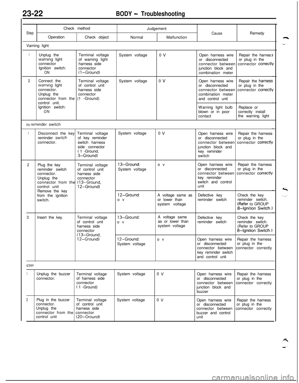
23-22BODY - TroubleshootingCheck method
StepOperation
Check object
Varning lightJudgementCauseRemedy
NormalMalfunction
1Unplug theTerminal voltagewarnrng light
of warning light
connector
harness side
Ignition switch:
connector
ON(I-Ground)
2Connect the
Terminal voltagewarnrng light
of control unit
connector.
harness side
Unplug theconnector
connector from the (1 -Ground)
control unit.
Ignition switch:
ON
ey reminder switchSystem voltage
System voltage0 V
0 VOpen harness wireRepair the harnes:
or disconnectedor plug in the
connector between connector
correct1junction block and
combination meter
Open harness wireRepair the harries:
or disconnectedor plug in the
connector between connector
correctl!combination meter
and control unit
Warning light bulbReplace or
blown or in poorcorrectly install
contactthe warning light
1Disconnect the key Terminal voltageSystem voltage0 VOpen harness wireRepair the harness
reminder switchof key reminder
or disconnectedor plug in the
connector.
switch harnessconnector between connector
correct11side connector
junction block and
t 1 -Ground,
key reminderS-Ground)switch
2Plug the key
Terminal voltage13-Ground:ovOpen harness wireRepair the harness
reminder switchof control unitSystem voltageor disconnectedor plug in the
connector.
harness sideconnector between connector
correct11Unplug theconnectorkey reminder
connector from the
(13-Ground,switch and control
control unit12-Ground)unit
Remove the key
from the ignition
12-Ground:A voltage same asDefective keyCheck the key
switch.ovor lower thanreminder switchreminder switch.
system voltage(Refer to GROUP
84gnition Switch.1
3Insert the key.Terminal voltage
13-Ground:A voltage same
as or lower thanDefective keyCheck the key
of control unit
ovreminder switchreminder switch.
harness sidesystem voltage
(Refer to GROUP
connector
84gnition Switch.1(13-Ground,12-Ground)12-Ground:ovOpen harness wireRepair the harness
System voltageor disconnectedor plug in the
connector between connector correctly
key reminder switch
and control unit
lzzer
1Unplug the buzzer
Terminal voltageSystem voltage0 VOpen harness wireRepair the harness
connector.of harness side
or disconnectedor plug in the
connector
connector between connector correctly
t 1 -Ground)
junction block and
buzzer
2Plug in the buzzer
Terminal voltageSystem voltage0 VOpen harness wireRepair the harness
connector.
of control unit
or disconnectedor plug in the
Unplug the
harness side
connector between connector correctly
connector from the connector
buzzer and control
control unit
(20-Ground)unit
Page 1078 of 1216
23-34BODY - Hood
HOOD
REMOVAL AND INSTALLATION
N23HAA8
1518AO751
18A0438
LRemoval5
1.Bumper
2.Hood weatherstrip
3.Heat protector4.Hood weatherstrip
5. Headlight hood protector
I)+ 6.Bumper7. Hood support rod
8.Bumper9. Hood switch
theft-alarm system
>10.Bumper11.Bumper bracketl *I 12. Hood lock release handlel 13. Hood latch
NOTE
(1) Reverse the removal procedures to reinstall.(2) l 4 : Refer to “Service Points of Installation”.Hood lock release cable removal steps
l 12. Hood lock release handle
w 13. Hood latch
14. Protector15. Hood lock release cable
Hood removal steps
;f3: “,;n,yction for washer tube and nozzle
Hood hinge removal steps
17: ig?ction for washer tube and nozzle
Windshield wiper arms (Refer to GROUP
8-Windshield Wiper.)
18. Front deck garnish
,*I 19. Hood hinge
1
INSPECTIONHOOD SWITCH(I
1 Disconnect the hood switch connector.
(2) Check the continuity between the terminal.
WA0754lBRO665
)
NOTE
m indicates that there is continuity between the terminals.
Page 1079 of 1216
BODY - Hood23-35
SERWCE POINTS OF INSTALLATION
19. APPLICATION OF GREASE TO HOOD HINGE/IS. HOODLATCH/12.
HOOD LOCK RELEASE HANDLEApply multipurpose grease to all moving parts.
Grease: MOPAR Multipurpose Grease Part No.
2932524 or equivalent
Front end upper bar
18AO3926. INSTALLATION OF BUMPER
Install the bumper so that the amount of projection from thefront end upper bar is as shown in the illustration.
Page 1080 of 1216

23-36BODY - Liftgate
LIFTGATEN230AAT
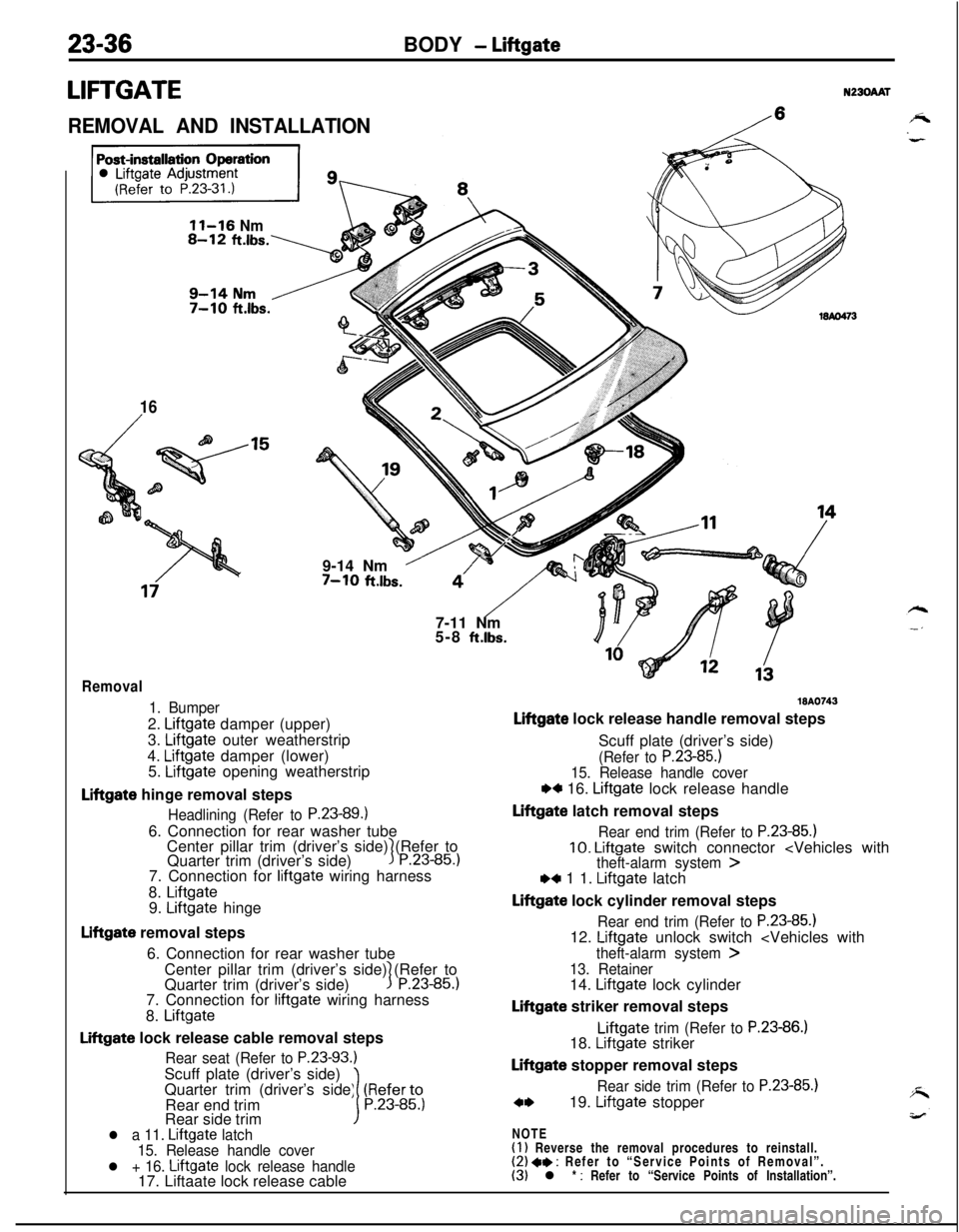
REMOVAL AND INSTALLATION/
11-16 Nm
16
/9-14 Nm
’7-10 ft.lbs.
“‘/- -$j7-11 Nm
5-8
ft.lbs.
Removal
1. Bumper2.
Liftgate damper (upper)
3.
Liftgate outer weatherstrip
4.
Liftgate damper (lower)
5. Liftgate opening weatherstrip
Liftgate hinge removal steps
Headlining (Refer to P.23-89.16. Connection for rear washer tube
Center pillar trim (driver’s side) (Refer to
Quarter trim (driver’s side)
3P.23-85.)7. Connection for
liftgate wiring harness
8.
Liftgate9. Liftgate hinge
Liftgate removal steps
6. Connection for rear washer tube
Center pillar trim (driver’s side) (Refer to
Quarter trim (driver’s side)
1P.23-85.)7. Connection for
liftgate wiring harness
8.
Liftgate
Liftgate lock release cable removal steps
Rear seat (Refer to P.23-93.)Scuff plate (driver’s side)
Quarter trim (driver’s side) (Referto
Rear end trim
1P.23-85.)Rear side trim
l a 11. Liftgate latch
15. Release handle cover
l + 16. Liftgate lock release handle17. Liftaate lock release cable
WA0743
Liftgate lock release handle removal steps
Scuff plate (driver’s side)
(Refer to P.23-85.)15. Release handle cover
w 16. Liftgate lock release handle
Liftgate latch removal steps
Rear end trim (Refer to P.23-85.)10. Liftgate switch connector ,4 1 1. Liftgate latch
Liftgate lock cylinder removal steps
Rear end trim (Refer to P.23-85.112. Liftgate unlock switch
theft-alarm system >
13. Retainer14. Liftgate lock cylinder
Liftgate striker removal stepsLiftgate
trim (Refer to P.23-86.)18. Liftgate striker
Liftgate stopper removal steps
Rear side trim (Refer to P.23-85.)
c*19. Liftgate stopper
NOTE
(1) Reverse the removal procedures to reinstall.(2) 4* : Refer to “Service Points of Removal”.(3) l * : Refer to “Service Points of Installation”.
Page 1081 of 1216
BODY - Liftnate23-37
SERVICE POINTS OF REMOVAL
19. REMOVAL OF LIFTGATE STOPPER
Caution
1. Never try to disassemble the liigate gas spring or
bum it.
2. Always bore a hole in the gas
spring to release the
interior gas before the spring is discarded.
INSPECTION
LIFTGATE SWITCH(I
1 Unlock the liftgate latch.
(2) Check the continuity between the terminals.
Terminal
Liftgate latch locked
Liftgate latch unlocked
1200
NOTE
o(> indicates that there is continuity between the terminals.
LIFTGATE LOCK CYLINDER SWITCH
Check to be sure that there is continuity between connector
terminals 1 and 2 when the switch part shown in the illustrationis not pressed, and that there is no longer continuity when it is
pressed.
SERVICE POINTS OF INSTALLATION
16.APPLlCATlON OF GREASE TO LIFTGATE LOCK
RELEASE HANDLE/ 11. LIFTGATE LATCHApply multipurpose grease to all moving parts.
Grease: MOPAR Multipurpose Grease Part No.
2932524 or equivalent
Page 1082 of 1216
23-38BODY - Fuel Tank Filler Door
FUEL TANK FILLER DOOR
REMOVAL AND INSTALLATIONN23JAA0
Pre-removal Operatione Removal of Rear Seat
(Refer to P.23-93.)0 Removal of Rear Side Trim, Quart-
er Trim and Scuff Plate.
(Refer to
P.23-85.)
Post-installation Operationl Installation of Rear Side Trim,
Quarter Trim and Scuff Plate
(Refer to
P.23-85.)0 Installation of Rear Seat
(Refer to P.23-93.)0 Fuel Filler Door Adjustment
(Refer to P.23-31.)
Removal stepsl C 1. Fuel filler door
2. Fuel filler door hook
3. Release handle cover
l + 4. Fuel filler door lock release handle
5. Fuel filler door lock release cable16A0462NOTE
(I 1 Reverse the removal procedures to reinstall.(2) l * : Refer to “Service Points of Installation”.
SERVICE POINTS OF INSTALLATION4.
APPLICATION OF GREASE TO FUEL FILLER DOOR LOCK
RELEASE HANDLE/l. FUEL FILLER DOORApply multipurpose grease to all moving parts.
Grease: MOPAR Multipurpose Grease Part No.
2932524 or equivalent
Page 1097 of 1216
BODY - Loose Panel
LOOSE PANEL
- REMOVAL AND INSTALLATION
, Frbnt
piI@ (LH),/
N22SAAK ,
-.
v trayFront deck
crossmember
+ADeck crossmember stay
/Front
I
‘-9-14 Nm7-10 ftlbs.slaememoer
mWaterproof plate\K?%--
(RH)
WA0471Headlight supportWA.0741
,
/
WA0463, Headlight support
/-c---x/
I IHood lock support
_Headlight supporte duct
MA0742
WA0472
e Dumper,18AO484