Page 1112 of 1216
23-68BODY - Power Window
Power
window
lock
switch
,POWER WINDOW MOTOR
(1) Connect the motor terminal directly to the battery and
check to be sure that the slider moves smoothly.
(2) Also check to be sure that the slider moves in the opposite
direction when the battery polarity connections are
changed.CIRCUIT BREAKER (INCORPORATED IN THE POWER
WINDOW
MOTOR)
(1) Press the UP switch to fully close the window glass, and
continue to press the switch for
10 seconds.
(2) At the moment that the UP switch is released, press the
DOWN switch. The circuit breaker can be considered goodif at this time the door window glass begins to open within
60 seconds.POWER WINDOW MAIN SWITCH
Check for continuity in accordance to the following connection
table.
NOTEO-O indicates that there is continuity between the terminals.
Page 1113 of 1216

BODY - Power Window/Door Handle and Latch23-69
I-
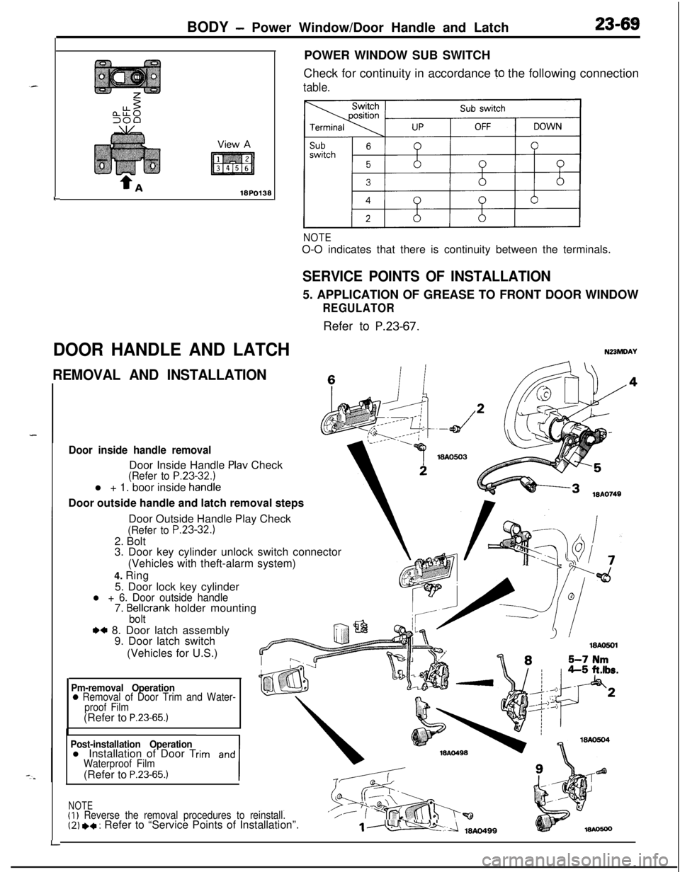
DOOR HANDLE AND LATCHPOWER WINDOW SUB SWITCH
Check for continuity in accordance
10 the following connection
table.
NOTEO-O indicates that there is continuity between the terminals.
SERVICE POINTS OF INSTALLATION5. APPLICATION OF GREASE TO FRONT DOOR WINDOW
REGULATORRefer to
P.23-67.
N23MDAY
REMOVAL AND INSTALLATIONc
Door inside handle removalDoor Inside Handle
Plav Check(Refer to P.23-32.1l + 1. boor inside
handieDoor outside handle and latch removal steps
LDoor Outside Handle Play Check
(Refer to P.23-32.)2. Bolt
3. Door key cylinder unlock switch connector
(Vehicles with theft-alarm system)
4. Ring
5. Door lock key cylinder
l + 6. Door outside handle7. Bellcrank holder mountingbolt
.a 8. Door latch assembly
9. Door latch switch
(Vehicles for U.S.)
Pm-removal Operation0 Removal of Door Trim and Water-
proof Film(Refer to
P.23-65.)
Post-installation Operationl Installation of Door Trim and
1
Waterproof Film(Refer to P.23-65.)
NOTE(I)
Reverse the removal procedures to reinstall.‘/(2) *+ : Refer to “Service Points of Installation”.1m
Page 1114 of 1216

23-70BODY- Door Handle and Latch/Central Door Lockina Svstem
I18AO750 1lBY3611 I.- .--,
!-
II
T!3123
18PO39i
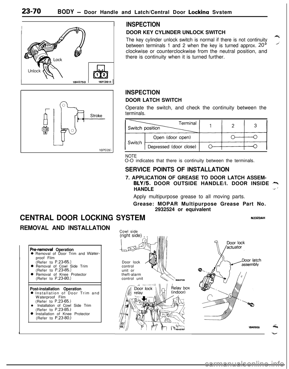
INSPECTIONDOOR KEY CYLINDER UNLOCK SWITCH
The key cylinder unlock switch is normal if there is not continuity7
between terminals 1 and 2 when the key is turned approx. 20”’clockwise or counterclockwise from the neutral position, and
there is continuity when it is turned further.
INSPECTIONDOOR LATCH SWITCH
Operate the switch, and check the continuity between the
terminals.
NOTEO-O indicates that there is continuity between the terminals.
SERVICE POINTS OF INSTALLATION7. APPLICATION OF GREASE TO DOOR LATCH ASSEM-
BLY/5. DOOR OUTSIDE HANDLE/l. DOOR INSIDE rr,
HANDLE.< ‘Apply multipurpose grease to all moving parts.
Grease: MOPAR Multipurpose Grease Part No.
2932524 or equivalent
CENTRAL DOOR LOCKING SYSTEMN23ZDAI-I
REMOVAL AND INSTALLATION
Pre-removal Operation0 Removal of Door Trim and Water-
Iproof Film
(Refer to P.23-65.)
0 Removal of Cowl Side Trim
(Refer to P.23-85.)
0 Removal of Knee Protector
(Refer to P.23-80.)
Post-installation Operation0 Installation of Door Trim and
Waterproof Film
(Refer to P.23-65.)
l Installation of Cowl Side Trim
(Refer to P.23-85.)
0 Installation of Knee Protector
(Refer to P.23-80.)
ICowl side
(right side) , ,
Door lock
control
unit or
theft-alarm
control unit
Page 1115 of 1216

BODY - Central Door Locking System/Door Runchannel23-71View A
18A0064-
L
DOOR RUNCHANNEL
REMOVAL AND INSTALLATION
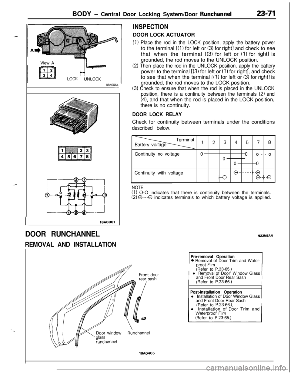
INSPECTIONDOOR LOCK ACTUATOR
(1) Place the rod in the LOCK position, apply the battery powerto the terminal
i(l) for left or (3) for right1 and check to see
that when the terminal
L(3) for left or (I) for right1 is
grounded, the rod moves to the UNLOCK position.
(2) Then place the rod in the UNLOCK position, apply the batterypower to the terminal
L(3) for left or (I 1 for right], and check
to see that when the terminal
[(l ) for left or (3) for right1 is
grounded, the rod moves to the LOCK position.
(3) Check to ensure that when the rod is placed in the UNLOCK
position, there is a continuity between the terminals
12) and
(41, and that when the rod is placed in the LOCK position,
there is no continuity.
DOOR LOCK RELAYCheck for continuity between terminals under the conditions
described below.
,2345, 8Continuity
novoltage0
0o--o
0
00
Continuity with voltage
@- -----@
@--0
NOTE
(1) O-O indicates that there is continuity between the terminals.
(2) O---O indicates terminals to which battery voltage is applied.
N23MEAN
Pre-removal Operation0 Removal of Door Trim and Water-
_ -..proot Mm
(Refer to
P.23-65.11 l Removal of Door’ Window Glass 1Iand Front Door Rear SashI(Refer to P.23-66.)IDoor window
runchannel
Post-installation Operationl Installation of Door Window Glass
and Front Door Rear Sash
(Refer to
P.23-66.1Il Installation of Dbor Trim and
Runchannel
18A0465
Page 1124 of 1216
23-80BODY - Instrument Panel
REMOVAL AND INSTALLATION
-?7
Removal steps
1. Plug2. Knee protecter assembly
3. Hood lock release handle
4. Column cover lower
5. Column cover upper
6. Cover
(A)7. Cluster panel assembly (A)8. Radio panel9. Radio or radio and tape player
10. Center air outlet assembly
11. Dial knob (A)12. Cluster panel assembly (B)13. Stopper
14. Glove box assembly
Nm6-9 ft.lk.15. Combination meter
16. Speedometer cable adapter
17. Speaker garnishes18. Bracket
19. Heater control assembly installation
screws
20. Lap cooler duct
21. Shower duct (L.H.122. Steering shaft mounting bolt(s)23. Instrument panel mounting screws
24. Instrument panel mounting bolts
25. Instrument panel assembly
NOTE(1) Reverse the removal procedures to reinstall.(2) l * : Refer to “Service Points of Removal”
Page 1125 of 1216
BODY - Instrument Panel23-81
SECT. A-A
Flat-tip
( - ) screwdriver19A0274
1910267
SERVICE POINTS OF REMOVAL
10. REMOVAL OF CENTER AIR OUTLET ASSEMBLY
Removing the paw1 of the center air outlet assembly with aflat-tip
( - 1 screwdriver,remove the center air outlet
assembly with the plastic trim tool.
16. REMOVAL OF SPEEDOMETER CABLE ADAPTER
(1) Disconnect the speedometer cable at the transaxle endof the cable.
(2) Pull the speedometer cable slightly toward the vehicle
interior, release the lock by turning the adapter to the leftor right, and then remove the adapter.
Page 1126 of 1216
23-82BODY - Instrument Panel
9N23
Cluster panel (A) disassembly steps
1. Switch holder (A)2. Headlight pop-up switch
3. Plug
(A)4. Rheostat
5. Cluster panel
(A)
Cluster panel (B) disassembly steps6. Switch holder
(5)7. Hazard switch
8.
p;Fr window defogger switch or plug
9.
$far wiper and washer switch or plug10. Heater control panel assembly
II. Cluster panel (B)
Knee protector disassembly steps12. Lap cooler grill assembly
13. Knee protector
Glove box disassembly steps14. Glove box lock assembly
15. Glove box pad
16. Glove box hinge
17. Glove box
Instrument panel disassembly steps18. Glove box light switch
19. Lower frame
20. Corner pad21. Glove box striker
22. Glove box light bracket
23. Speakers
Page 1128 of 1216