Page 1046 of 1216

23-2
SPECIFICATIONS
GENERAL SPECIFICATIONS
BODY - Specifications
N23CA--
Items
Hood
We
Door
Construction
Regulator system
Locking system
Liftgate
We
Slass installation method
Windshield glass
Quarter window glass
Liftgate window glass
Zlass thicknessmm (in.)
Windshield glass
Liftgate window glass
Door glass
Quarter window glass
‘ower window motor
Type
Revolutions under no loadwm
Revolutions under load
wmAt 1
Nm t.72 ft.lbs.1At 2
Nm (1.45 ft.lbs.1Bound current A
Direction of rotation
‘ower window main switch
Type
Rated load currentA
Lock switch
Power window switch
‘ower window sub switch
TvwRated load current A
‘ower window relay
Maximum contact currentA
Rated coil currentA
Voltage drop between terminalsV(At 12 V and the rated load current)
Specifications
Rear hinged, front opening type
Front-hinged, sash construction
Wire type
Pin-fork type
Inner-hinged, with gas damper
Adhesive type
Adhesive type
Adhesive type5.3
i.21)3.5
t.1413.5
t.1413.5
t.141
Permanent magnet type (Built-in circuit breaker)
75 or more65-95
50-80
34 or less
Clockwise and counter-clockwise
Automatic reset type
10
10
Automatic reset type
10
20
Max. 0.2
0.2 or less
Page 1050 of 1216

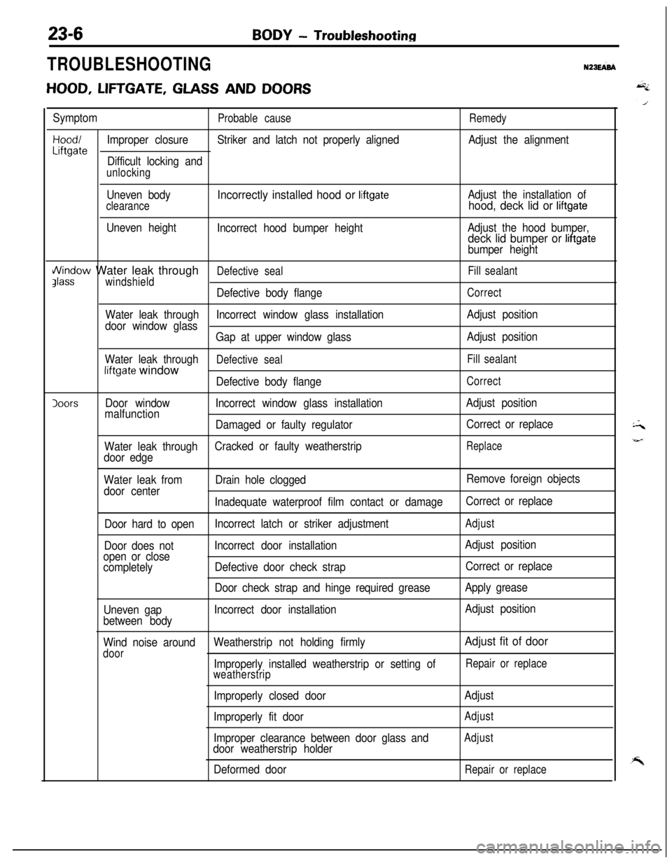
BODY - Troubleshooting
TROUBLESHOOTINGN23EFd
HOOD, LIFTGATE, GLASS AND DOORS
SymptomProbable causeRemedy
Hood/Improper closureStriker and latch not properly alignedAdjust the alignmentLiftgateDifficult locking and
unlocking
Uneven body
clearance
Uneven height
Incorrectly installed hood or liftgate
Incorrect hood bumper heightAdjust the installation of
hood, deck lid or liftgate
Adjust the hood bumper,deck lid bumper or liftgate
bumper height
i/\/indow Water leak throughDefective sealFill sealantJlasswindshield
Defective body flangeCorrect
Water leak throughIncorrect window glass installationAdjust position
door window glass
Gap at upper window glassAdjust position
Water leak through
Defective sealFill sealantliftgate window
Defective body flangeCorrect
IoorsDoor windowIncorrect window glass installationAdjust position
malfunction
Damaged or faulty regulatorCorrect or replace
Water leak throughCracked or faulty weatherstrip
Replace
door edge
Water leak fromDrain hole cloggedRemove foreign objects
door center
Inadequate waterproof film contact or damageCorrect or replace
Door hard to openIncorrect latch or striker adjustment
Adjust
Door does notIncorrect door installationAdjust position
open or close
completelyDefective door check strapCorrect or replace
Door check strap and hinge required greaseApply grease
Uneven gapIncorrect door installationAdjust position
between body
Wind noise aroundWeatherstrip not holding firmly
Adjust fit of door
doorImproperly installed weatherstrip or setting ofRepair or replace
weatherstrip
Improperly closed door
Improperly fit door
Improper clearance between door glass and
door weatherstrip holder
Deformed doorAdjust
Adjust
Adjust
Repair or replace
Page 1160 of 1216

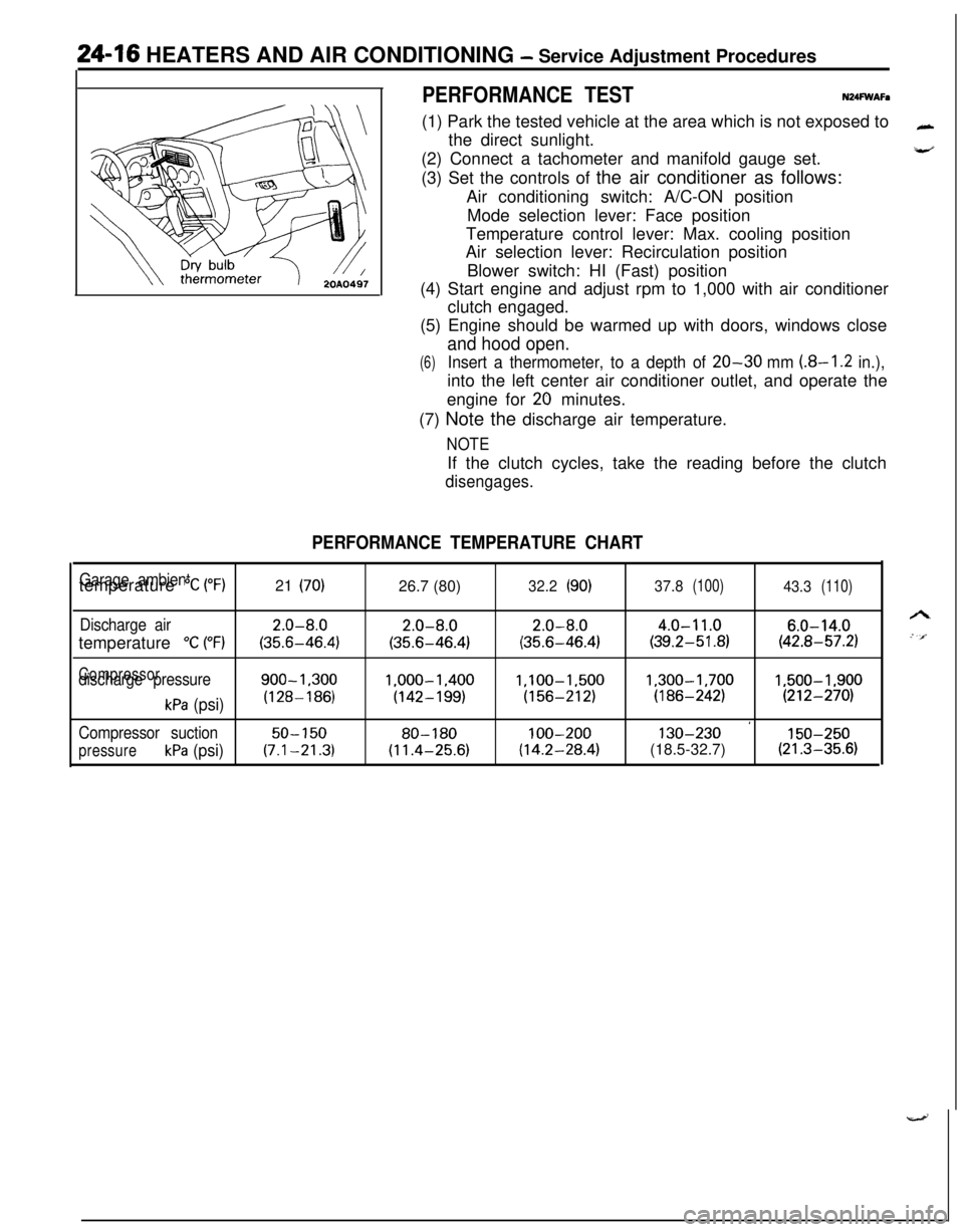
24-16 HEATERS AND AIR CONDITIONING - Service Adjustment Procedures
PERFORMANCE TESTN24FWAFa(1) Park the tested vehicle at the area which is not exposed to
the direct sunlight.
(2) Connect a tachometer and manifold gauge set.
(3) Set the controls of the air conditioner as follows:
Air conditioning switch: A/C-ON position
Mode selection lever: Face position
Temperature control lever: Max. cooling position
Air selection lever: Recirculation position
Blower switch: HI (Fast) position
(4) Start engine and adjust rpm to 1,000 with air conditioner
clutch engaged.
(5) Engine should be warmed up with doors, windows close
and hood open.
(6)Insert a thermometer, to a depth of 20-30 mm (8-I .2 in.),into the left center air conditioner outlet, and operate the
engine for
20 minutes.
(7) Note the discharge air temperature.
NOTEIf the clutch cycles, take the reading before the clutch
disengages.
PERFORMANCE TEMPERATURE CHART
Garage ambienttemperature “C (“F)21 (70)26.7 (80)32.2(90)37.8(100)43.3(110)
Discharge air2.0-8.02.0-8.02.0-8.04.0-11.06.0-14.0temperature
“C (“F)(35.6-46.4)(35.6-46.4)(35.6-46.4)(39.2-51.8)(42.8-57.2)
Compressordischarge pressure900-1.3001.000-1.400l,lOO-1,5001,300-1,7001,500-1,900
kPa (psi)(128-186)(142-199)(156-212)(186-242)(212-270)
’Compressor suction50-15080-180100-200130-230150-250
pressurekPa (psi)(7.1-21.3)(11.4-25.6)(14.2-28.4)(18.5-32.7)(21.3-35.6)
Page 1162 of 1216

24-18 HEATERS AND AIR CONDITIONING - Service Adjustment Procedures
(5) Screw a can of R-12 to the opened manifold valve. Be sure
gasket is in place and in good condition. Tighten refrigerantcan and manifold locking nut to insure a good seal. Do not
overtighten 8 to
11 Nm (6 to 8 ft.lbs.) is sufficient if gasket
is in good condition.
(6) Turn manifold valve (above the refrigerant can) completely
clockwise to puncture the can. This closes the valve and
seals the refrigerant in the can.
Caution
Never heat small cans of refrigerant over
40°C (104°F)as they may explode.
(7) Place the refrigerant in a large pan of water heated to 52°C
(104°F). Place pan of water containing the refrigerant can
on an accurate scale so the amount of refrigerant added
can be weighed. Open the refrigerant manifold valve.
(8) Purge all air from test hoses. Air in the system will be
trapped in the condenser causing abnormally high dis-
charge pressures and interfering with condensing of the
refrigerant.(9) Slightly loosen both test hoses at the gauge set manifold.
Tighten the hoses as soon as the air is purged.
(10)Slightly loosen charging hose connection at gauge set
manifold. This will purge air from the charging hose.
Tighten connection as soon as air is purged.
(I l)With vehicle windows open and hood up, operate engine at1,500 rpm and jump the low pressure switch terminals
located on the receiver drier so the clutch will remain
engaged.
(12)Place air conditioner control on air conditioner and place theblower switch on high.
(13)lf necessary, block the condenser to maintain a discharge
pressure of 1,422 to 1,520
kPa (206 to 220 psi). System
must be charged through the evaporator suction service
ports as follows:
(a) Slowly open the suction service gauge valve.
Meter flow of refrigerant by adjusting, the suciton
service gauge valve so that pressure registered at the
suction service gauge does not exceed 345 kPa (50 psi).Keep refrigerant container upright.
(b) Add refrigerant gas until there is no foam visible at the
sight glass.
Add an additional
170 g (6 oz.)
(c) Close the suction gauge valve.
CautionToo much refrigerant in the system can cause
abnormally high discharge pressures. Care must beused so that the exact recommended amount or
refrigerant is added after foam clears in the sight
glass.(d) Close dispensing manifold valve. Remove test hoses
and adapters from the service ports of compressor,
install protective caps at service ports and reconnect
wiring.(e) Check system performance.
(P.24- 16.)
e
. i”
A
i-4