1991 MITSUBISHI ECLIPSE catalytic converter
[x] Cancel search: catalytic converterPage 53 of 1216

FRONT SUSPENSION - Specifications2-5Items
Rear roll stopper bracket to centermember
Centermember installation bolts (front)
Centermember installation bolts (rear)
Joint assembly and gear box connecting bolt
Steering gear box assembly to return tube
Steering gear box assembly to pressure hose
Steering gear box assembly to crossmember
Pressure hose bracket to crossmember
Transfer installation bolt
Nmftlbs. I’, ‘,
40-5029-36
80-10058-72
80-I 0058-72
15-20II-1412-18
9-13
12-189-13
60-8043-58
9-14
7-10
55-6040-43
Gusset installation bolt
70-8051-58Left member installation bolt (front)
80-10058-72
Left member installation bolt (rear)
70-8051-58
Vo. 1 crossmember installation nut80-10058-72qight member installation bolt (front)
80-10058-72?ight member installation bolt (rear)
70-8051-58
+ont roll stopper to No. 1 crossmember40-5029-36
?ont roll stopper installation nut50-6536-47
Iront exhaust pipe to catalytic converter40-6029-43
‘rant exhaust pipe to hangerIO-157-11
‘-. LUBRICANTSNO2CD--
ItemsSpecified lubricantsQuantity
Outer surface of wheel bearing outer race
MOPAR Multi-mileage LubricantAs required
Wheel bearing inner racePart No. 2525035 or equivalent
Oil seal lip
Strut insulator bearing
Lower arm ball joint
Stabilizer link
Inner dust coverMOPAR Multi-mileage Lubricant
Part No. 2525035 or equivalent
7-10 g (.25-.35 oz.)
Outer dust cover
MOPAR Multi-mileage Lubricant
Part
No.2525035 or equivalent4-6
g (.14-.21 oz.)
B.J. boot grease
Repair kit grease
1.8L engine
95 g (3.4 oz.)
Vehicles with
2.0L DOHC engine110 g (3.9 oz.)
T.J. boot grease
Repair kit grease
1.8L engine105 g (3.7 oz.)
Vehicles with
2.0L DOHC engine120 g (4.2 oz.)
Spider assemblyRepair kit greaseAs required
NOTEThe grease in the repair kit should be divided in half for use, respectively, at the joint and inside the boot.
Page 426 of 1216

11-4INTAKE AND EXHAUST- Specifications/Special Tool/Troubleshooting
ItemsEngine oil level gauge guide mounting bolt
Engine hanger to engine
Exhaust manifold to engine
Exhaust manifold to turbocharger
Oil pipe to engine
Water pipe
(B) to water inlet pipe
Waste gate actuator
Oxygen sensor
Water pipe
(B) to turbocharger
Air outlet fitting
Oil pipe to turbocharger
Water pipe (A) to turbocharger
Water pipe (A) mounting bolt
Exhaust fitting
Oil return pipe
Exhaust pipe and main muffler
Front exhaust pipe to exhaust manifold
Front exhaust pipe to exhaust fitting
Front exhaust pipe clamp
Rubber hangerFront exhaust pipe to catalytic converter
Catalytic converter to center exhaust pipe
Hanger bracket to body
Hook to center exhaust pipe
Center exhaust pipe to main muffler
Moulding to main muffler
Nmft.lbs.
12-15
9-l 112-159-11
25-3018-?255-65
40-4714-19
IO-l+
40-5029-36
IO-137-9
40-5029-36
35-5025-36
9-14
7-1028-34
20-25
35-5025-36
IO-127-9
55-65
40-47
8-106-7
30-4022-29
40-6029-43
30-4022-29
IO-157-11
40-6029-43
30-4022-29
10-157-11
10-157-11
30-4022-29
4-63-4
TROUBLESHOOTINGNllEAAB
Symptom
Exhaust gas leakage
Abnormal noiseProbable cause
Loose joints
Broken pipe or muffler
Broken separator in muffler
Broken rubber hangersInterference of pipe or muffler with vehicle body
Broken pipe or mufflerRemedy
Retighten
Repair or replace
Replace
Correct
Repair or replace
.-*
SPECIAL TOOLNllDA-
I ToolNumberNameI UseIRemoval/Installation of oxygen sensor
Removal/Installation of oxygen sensor
Fs\
Page 452 of 1216

lNTAKE AND EXHAUST _ Exhaust Pspe and Main Mufflerc 1.8L Engine, 2.0L DOHC Engine (Non-Turbo) >
EXHAUST PIPE AND MAIN MUFFLER
< I .8L Engine, 2.0L DOHC Engine (Non-Turbo)>
REMOVAL AND INSTALLATIONN1lRA-A
021’
IO-15 Nm7- 11 ft.lbs.
IO-15 Nm 22-29 ft.lbs.7- 11 ft.lbs.
OSAO144
30-k) Nm22-29 ft.lbs.40-60 Nm29-43 ft.lbs.30-&o
Nm22-29 ft.lbs.
Removal steps
1.Protector
2.Gasket
3.Hanger
4.Main muffler5. Moulding <2.0L DOHC engine (Non-Turbo)>
6.Hanger bracket
7. Rear heat protector panel8.Self locking nut9.O-ringIO. Hook11. Bracket12.Stopper
13.Hanger bracket14.Hanger15. Protector
16.Hanger bracket
17.Center exhaust pipe
18.Gasket
19.Catalytic converter
20. Gasket21. Self locking nut
22.Hanger23..Front exhaust pipe24.Gasket25. Front floor heat protector panel
NOTE(I 1 Reverse the removal procedures to reinstall.(2) q : Non-reusable parts
INSPECTIONNHRCAHOl Check
the mufflers and pipes for corrosion or damage.
l
Check the rubber hangers and rubber O-rings for
deterioration or damage.
l Check
for gas leakage from mufflers and pipes.
Page 454 of 1216

Removal steps
1.Protector
2.Gasket3.Hanger4.Main muffler5.Hanger bracket6. Rear heat protector panel
7. Self locking nut
8.O-ring
9.Hook10.Bracket11.Stopper12.Hanger bracket
13.Hanger14.Protector15.Hanger bracket
16. Center exhaust pipe17.Gasket18.Catalyticconverter19.Gasket20. Self locking nut21.Hanger22. Front exhaust pipe
23.Gasket24. Front floor heat protector panel
NOTE
t(1) Reverse the removal procedures to reinstall(21 q : Non-reusable parts
INSPECTIONNllRCAHl
l Check the mufflers
and pipes for corrosion or damage.0
Check the rubber hangers and rubber O-rings for
deterioration or damage.0
Check for gas leakage from mufflers and pipes.
Page 1197 of 1216

.^
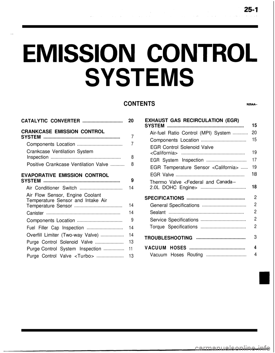
EMISSION CONTROL
SYSTEMS
CONTENTSN25AA-
CATALYTICCONVERTER...............................20CRANKCASE EMISSION CONTROL
SYSTEM...........................................................7Components Location
...................................7Crankcase Ventilation System
Inspection......................................................8Positive Crankcase Ventilation Valve
...........8EVAPORATIVE EMISSION CONTROL
SYSTEM...........................................................9
AirConditionerSwitch.................................14Air Flow Sensor, Engine Coolant
Temperature Sensor and Intake Air
Temperature Sensor
.....................................14
Canister.........................................................14Components Location
...................................9
FuelFillerCapInspection............................14Overfill Limiter (Two-way Valve)
..................14
PurgeControlSolenoidValve......................13Purge Control
SystemInspection................11
PurgeControlValve
SYSTEM...........................................................15Air-fuel Ratio Control (MPI) System
............20Components Location
...................................15EGR Control Solenoid Valve
.................................................19
EGR
SystemInspection...............................17EGR Temperature Sensor
......19
EGR Valve.....................................................18
Therm0 Valve
SPECIFICATIONS.............................................2General Specifications
..................................2
Sealant..........................................................2Service Specifications
...................................2
TorqueSpecifications...................................2
TROUBLESHOOTING......................................3
VACUUMHOSES...........................................4
VacuumHosesRouting...............................4
Page 1198 of 1216

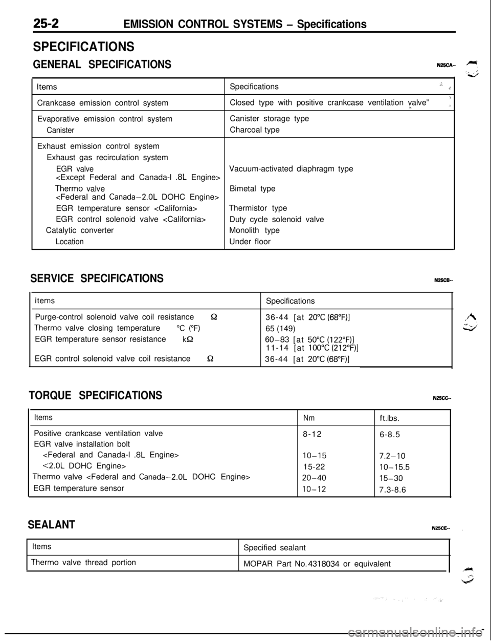
EMISSION CONTROL SYSTEMS - Specifications
SPECIFICATIONS
GENERAL SPECIFICATIONSN25CA-ItemsSpecifications
.,:..rCrankcase emission control systemClosed type with positive crankcase ventilation valve”I
‘:Evaporative emission control systemCanister storage type
CanisterCharcoal type
Exhaust emission control system
Exhaust gas recirculation system
EGR valveVacuum-activated diaphragm type
Therm0 valveBimetal type
EGR temperature sensor
EGR control solenoid valve
Duty cycle solenoid valve
Catalytic converterMonolith type
LocationUnder floor
SERVICE SPECIFICATIONSN25CB-
ItemsSpecifications
Purge-control solenoid valve coil resistance
&236-44 [at 20°C (68”F)I
Therm0 valve closing temperature“C (“F)65 (149)
EGR temperature sensor resistance
kQ60-83 [at 50°C (122”F)]11-14 [at
100°C (212”F)]EGR control solenoid valve coil resistance
S236-44 [at 20°C (68”F)]
TORQUE SPECIFICATIONSN25CC-
ItemsPositive crankcase ventilation valve
EGR valve installation bolt
<2.0L DOHC Engine>
Therm0 valve
EGR temperature sensor
Nmftlbs.8-12
6-8.5
IO-157.2-1015-22
10-15.5
20-4015-30
10-127.3-8.6
SEALANT
Items
Therm0 valve thread portionSpecified sealant
MOPAR Part No.4318034 or equivalent
Page 1216 of 1216

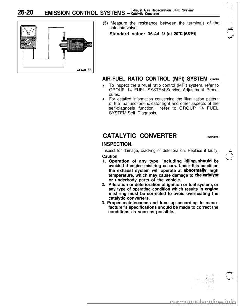
25-20Exhaust Gas Recirculation (EGR) System/EMISSION CONTROL SYSTEMS - ‘catalytic Converter(5) Measure the resistance between the terminals
of- the
Q [at 20°C (68OF)l
6EM0188
AIR-FUEL RATIO CONTROL (MPI) SYSTEM &CAD
lTo inspect the air-fuel ratio control (MPI) system, refer to
GROUP 14 FUEL SYSTEM-Service Adjustment Proce-
dures.
lFor detailed information concerning the illumination patternof the malfunction-indicator light and other aspects of the
self-diagnosis function,refer to GROUP 14 FUEL
SYSTEM-Self Diagnosis.
CATALYTIC CONVERTERN25lCBHa
INSPECTION.
Inspect for damage, cracking or deterioration. Replace if faulty.
Caution1. Operation of any type, including
idjing, should be
avoided if engine misfiring occurs. Under this conditionthe exhaust system will operate at abnormally ‘high
temperature, which may cause damage to
the”Catalystor underbody parts of the vehicle.
2.Alteration or deterioration of ignition or fuel system, or
any type of operating condition which results in enghtemisfiring must be corrected to avoid overheating the
catalytic converters.
3. Proper maintenance and tune up according to manu-
facturer’s specifications should be made to correct the
conditions as soon as possible.