Page 1016 of 1216
21-322AUTOMATIC TRANSAXLE - speedometer Gear AssemMylKickdown Servo
SPEEDOMETER GEAR ASSEMBLY
DISASSEMBLY AND REASSEMBLYNzlLaA6+.
201076
NOTE(1) Reverse the disassembly procedures to reassemble.(2) l : Refer to “Service Points of Reassembly”.(3) q : Non-reusable parts
Disassembly steps
1. O-ring
l + 2. Spring pin
H 3. Speedometer driven gear
4. Oil seal
5. Sleeve
SERVICE POINTS OF REASSEMBLY
3. INSTALLATION OF SPEEDOMETER DRIVEN GEARApply gear oil sparingly to the speedometer driven gear
shaft and insert the shaft.“c,
2. INSTALLATION OF SPRING PINL_,
Install the spring pin in such a way that its slit does not facethe gear shaft.
Slit201079
KICKDOWN SERVONZlLPAE
DISASSEMBLY AND REASSEMBLY
Disassembly steps
I. O-ring2. Kickdown servo
3. D-ring
4. Seal rina
65.
Locknuj6. Kickdown servo rod
7. Kickdown servo piston1750299
NOTE(1) Reverse the disassembly procedures to reassemble.
(2) m : Non-reusable parts
Page 1018 of 1216
21-324AUTOMATIC TRANSAXLE - Valve Body
VALVE BODY
DISASSEMBLY AND REASSEMBLYViewed from A
NZlLOAK
-0 - -
8
TFA0523
Disassembly steps
1. Manual valve
l +2. Pressure control solenoid valvel +3. Damper clutch control solenoid v
l +4. Shift control solenoid valve “A”
l +5. Shift control solenoid valve “B”6. Clamp
7. Valve stopper
8. N-D control sleeve
9. N-D control valve
l + 10. Lower valve body sub assembly11. Lower separating plate12.Nut13.Jet
l + 14. Relief spring
l + 15. Steel ballH 16. Oil filterW 17. Upper valve body sub assemblyWI
18. Steel ball
H 19. Teflon balll 420.N-Delate
NOTE(1) Reverse the disassembly procedures to reassemble.(2) l 4 : Refer to “Service Points of Reassembly”.
21. Block22. Upper separating plate
23. Intermediate plate
Page 1032 of 1216
21-338AUTOMATIC TRANSAXLE- Transfer Case Adapter Sub Assembly 4W4A33>
TRANSFER CASE ADAPTER SUB ASSEMBLY N21VlAADISASSEMBLY
AND REASSEMBLY
Disassembly steps
4**+1.Locknut
4*2. Driven bevel gear
I)4 3. Taper roller bearing
*4 ;. ;z;;r
6:Outer race
7.Outer race
8. Transfer case adapter
4e W 9. Taper roller bearing
NOTE(I) Reverse the disassembly procedures to reassemble.(2) 4e : Refer to ::Service Points of Disassembly:‘.[j &@ j Refer to Service Points of Reassembly
Non-reusable parts
140-150 Nm102-115 ft.lbs.
TEA0 604
SERVICE POINTS OF DISASSEMBLY
1. REMOVAL OF LOCK NUT
(1) Unstake the lock nut.
I IMB991013
TFAO289(2) Remove the driven bevel gear’s lock nut by using the
special tool.
Page 1034 of 1216
21-340 AUTOMATIC TRANSAXLE -Transfer Case Adapter Sub Assembly Fb
MD99881 2
MD99881 4
MD998822
TFAO311
3. INSTALLATION OF TAPER ROLLER BEARINGUsing the special tool, install the taper roller bearing.
1. INSTALLATION OF LOCK NUT
(1) Tighten the driven bevel gear’s lock nut at the specifiedtorque by using the special tool.
(2) Stake the lock nut at two places for locking.
Page 1045 of 1216

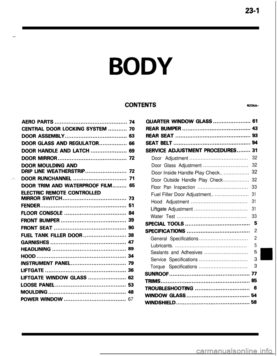
23-lBODY
CONTENTSN23Ak-
AERO PARTS..........................................74
CENTRAL DOOR LOCKING SYSTEM...........70
DOOR ASSEMBLY....................................63
DOOR GLASS AND REGULATOR................66
DOORHANDLEANDLATCH.....................69
DOOR MIRROR........................................72
DOOR MOULDING AND
DRIP LINE WEATHERSTRIP........................72
....DOOR RUNCHANNEL...............................71
DOOR TRIM AND WATERPROOF FILM........65
ELECTRIC REMOTE CONTROLLED
MIRROR SWITCH.....................................73
FENDER..................................................51
FLOOR CONSOLE....................................84
FRONT BUMPER......................................39
FRONT SEAT..........................................90
FUEL TANKFILLERDOOR.........................38
GARNISHES............................................47
HEADLINING...........................................89
HOOD....................................................34
INSTRUMENT PANEL................................79
LIFTGATE...............................................36
LIFTGATE WINDOWGLASS......................62
LOOSE PANEL.........................................53
MOULDING.............................................48
POWER WINDOW....................................67
QUARTERWINDOWGLASS......................61
REAR BUMPER........................................43
REAR SEAT............................................93
SEAT BELT.............................................94
SERVICE ADJUSTMENT PROCEDURES........31
Door Adjustment....................................32
Door Glass Adjustment............................32Door Inside Handle Play Check..................
32
Door Outside Handle Play Check................32
Floor PanInspection...............................
33Fuel Filler Door Adjustment.......................
31
Hood Adjustment...................................31
Liftgate Adjustment.................................31
Water Test...........................................33
SPECIAL TOOLS......................................5
SPECIFICATIONS.....................................2
General Specifications..............................
2
Lubricants.............................................5
Sealants and Adhesives...........................5
Service Specifications..............................3
Torque Specifications..............................3
SUNROOF...............................................77TRIMS
....................................................85
TROUBLESHOOTING................................6WINDOW
GLASS.....................................54
WINDSHIELD...........................................58
Page 1046 of 1216

23-2
SPECIFICATIONS
GENERAL SPECIFICATIONS
BODY - Specifications
N23CA--
Items
Hood
We
Door
Construction
Regulator system
Locking system
Liftgate
We
Slass installation method
Windshield glass
Quarter window glass
Liftgate window glass
Zlass thicknessmm (in.)
Windshield glass
Liftgate window glass
Door glass
Quarter window glass
‘ower window motor
Type
Revolutions under no loadwm
Revolutions under load
wmAt 1
Nm t.72 ft.lbs.1At 2
Nm (1.45 ft.lbs.1Bound current A
Direction of rotation
‘ower window main switch
Type
Rated load currentA
Lock switch
Power window switch
‘ower window sub switch
TvwRated load current A
‘ower window relay
Maximum contact currentA
Rated coil currentA
Voltage drop between terminalsV(At 12 V and the rated load current)
Specifications
Rear hinged, front opening type
Front-hinged, sash construction
Wire type
Pin-fork type
Inner-hinged, with gas damper
Adhesive type
Adhesive type
Adhesive type5.3
i.21)3.5
t.1413.5
t.1413.5
t.141
Permanent magnet type (Built-in circuit breaker)
75 or more65-95
50-80
34 or less
Clockwise and counter-clockwise
Automatic reset type
10
10
Automatic reset type
10
20
Max. 0.2
0.2 or less
Page 1047 of 1216

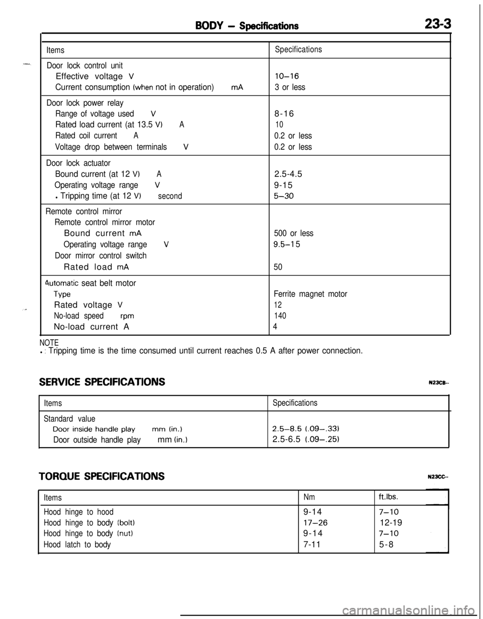
BODY - Specifications23-3
Items
Door lock control unitEffective voltage
V
Current consumption (when not in operation)
Door lock power relay
Range of voltage used
V
Rated load current (at 13.5 VIA
Rated coil currentA
Voltage drop between terminalsV
Door lock actuator
Bound current (at 12 VIA
Operating voltage rangeV
l Tripping time (at 12 V)second
Remote control mirror
Remote control mirror motorBound current
mA
Operating voltage range
V
Door mirror control switchRated load
mA
4utomatic seat belt motor
TypeRated voltage
V
No-load speedwmNo-load current A
mASpecifications
lo-16
3 or less8-16
10
0.2 or less
0.2 or less2.5-4.5
9-15
5-30
500 or less
9.5-l 5
50
Ferrite magnet motor
12
140
4
NOTEl : Tripping time is the time consumed until current reaches 0.5 A after power connection.
SERVICE SPECIFICATIONSN23CB--
ItemsSpecifications
Standard valueDoor
inside handle playmm (in.)2.5-8.5 (.09-,331
Door outside handle playmm (in.)2.5-6.5 (.09-.25)
TORQUE SPECIFICATIONS
ItemsNmft.lbs.
Hoodhingetohood9-14
7-10
Hoodhingetobody(bolt)17-2612-19
Hoodhingetobody(nut)9-147-10
Hoodlatchtobody7-115-8
Page 1048 of 1216

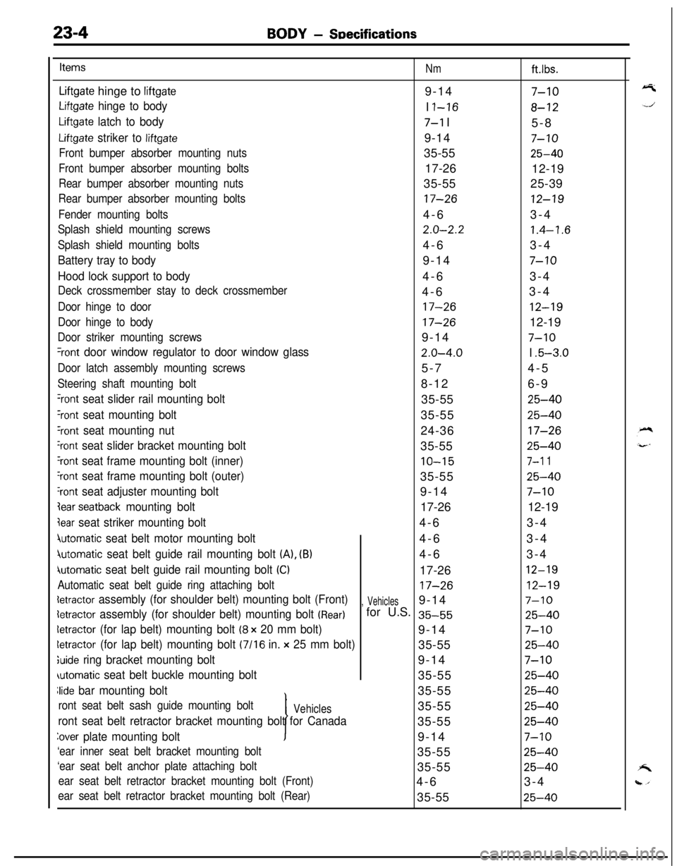
23-4BODY - SDecifications
Items
Nmft.lbs.
Liftgate hinge to liftgate9-147-10
Liftgate hinge to bodyI I-168-12
Liftgate latch to body7-l I
5-8
Liftgate striker to liftgate9-147-10
Front bumper absorber mounting nuts35-5525-40
Front bumper absorber mounting bolts17-26
12-19
Rear bumper absorber mounting nuts35-5525-39
Rear bumper absorber mounting bolts17-2612-19
Fender mounting bolts4-63-4
Splash shield mounting screws2.0-2.21.4-1.6
Splash shield mounting bolts4-63-4
Battery tray to body9-147-10
Hood lock support to body4-63-4
Deck crossmember stay to deck crossmember4-63-4
Door hinge to door17-2612-19
Door hinge to body17-2612-19
Door striker mounting screws9-147-10
%ont door window regulator to door window glass2.0-4.0I .5-3.0
Door latch assembly mounting screws5-74-5
Steering shaft mounting bolt8-126-9
‘rant seat slider rail mounting bolt35-5525-40
Yont seat mounting bolt35-5525-40
‘rant seat mounting nut24-3617-26
‘rant seat slider bracket mounting bolt35-5525-40
‘rant seat frame mounting bolt (inner)10-157-l 1
‘rant seat frame mounting bolt (outer)35-5525-40
‘rant seat adjuster mounting bolt9-147-10
lear seatback mounting bolt17-2612-19
jear seat striker mounting bolt4-63-4
4utomatic seat belt motor mounting bolt4-63-4
jutomatic seat belt guide rail mounting bolt (A), (B)4-63-4
iutomatic seat belt guide rail mounting bolt (Cl17-2612-19
Automatic seat belt guide ring attaching bolt17-2612-19
detractor assembly (for shoulder belt) mounting bolt (Front), Vehicles9-147-10
detractor assembly (for shoulder belt) mounting bolt (Rear)for U.S. 35-5525-40
detractor (for lap belt) mounting bolt (8 x 20 mm bolt)9-147-10
letractor (for lap belt) mounting bolt (7116 in. x 25 mm bolt)35-5525-40
;uide ring bracket mounting bolt9-147-10
automatic seat belt buckle mounting bolt35-5525-40
Jide bar mounting bolt
I35-55
25-40
ront seat belt sash guide mounting boltVehicles35-5525-40
ront seat belt retractor bracket mounting bolt for Canada35-5525-40
Zover plate mounting bolt9-147-10
‘ear inner seat belt bracket mounting bolt35-5525-40
‘ear seat belt anchor plate attaching bolt35-5525-40
ear seat belt retractor bracket mounting bolt (Front)4-63-4
ear seat belt retractor bracket mounting bolt (Rear)35-5525-40