Page 916 of 1216

21-222AUTOMATIC TRANSAXLE - Transaxle Control
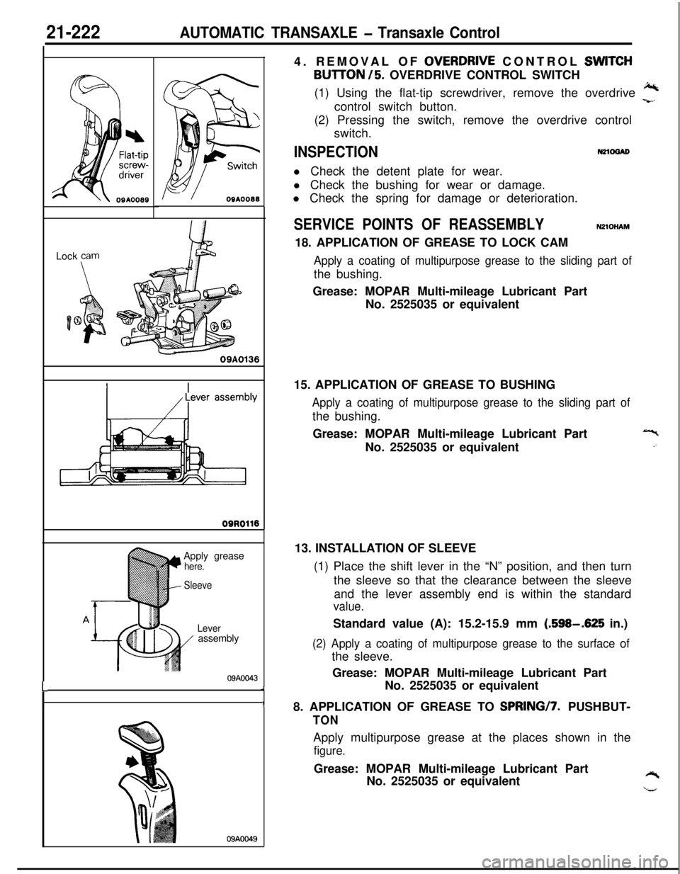
OSAOO88Lock
Farn
09A0136
09ROll6
LApply grease
here.
I
Sleeve
Lever/ assembly
09AOO43J
I
09AOO494. REMOVAL OF
OVERDRJVE CONTROL SWlTCH
BUlTON /5. OVERDRIVE CONTROL SWITCH
(1) Using the flat-tip screwdriver, remove the overdrive
J%control switch button.-r,(2) Pressing the switch, remove the overdrive control
switch.
INSPECTIONN21ocuDl Check the detent plate for wear.
l Check the bushing for wear or damage.
l Check the spring for damage or deterioration.
SERVICE POINTS OF REASSEMBLYNZlOHAM18. APPLICATION OF GREASE TO LOCK CAM
Apply a coating of multipurpose grease to the sliding part ofthe bushing.
Grease: MOPAR Multi-mileage Lubricant Part
No. 2525035 or equivalent
15. APPLICATION OF GREASE TO BUSHING
Apply a coating of multipurpose grease to the sliding part ofthe bushing.
Grease: MOPAR Multi-mileage Lubricant Part
No. 2525035 or equivalent
13. INSTALLATION OF SLEEVE
(1) Place the shift lever in the “N” position, and then turn
the sleeve so that the clearance between the sleeve
and the lever assembly end is within the standard
value.Standard value (A): 15.2-15.9 mm
(.598-.625 in.)
(2) Apply a coating of multipurpose grease to the surface ofthe sleeve.
Grease: MOPAR Multi-mileage Lubricant Part
No. 2525035 or equivalent
8. APPLICATION OF GREASE TO SPRINGI7. PUSHBUT-
TONApply multipurpose grease at the places shown in the
figure.Grease: MOPAR Multi-mileage Lubricant Part
No. 2525035 or equivalent
Y‘,#
Page 923 of 1216

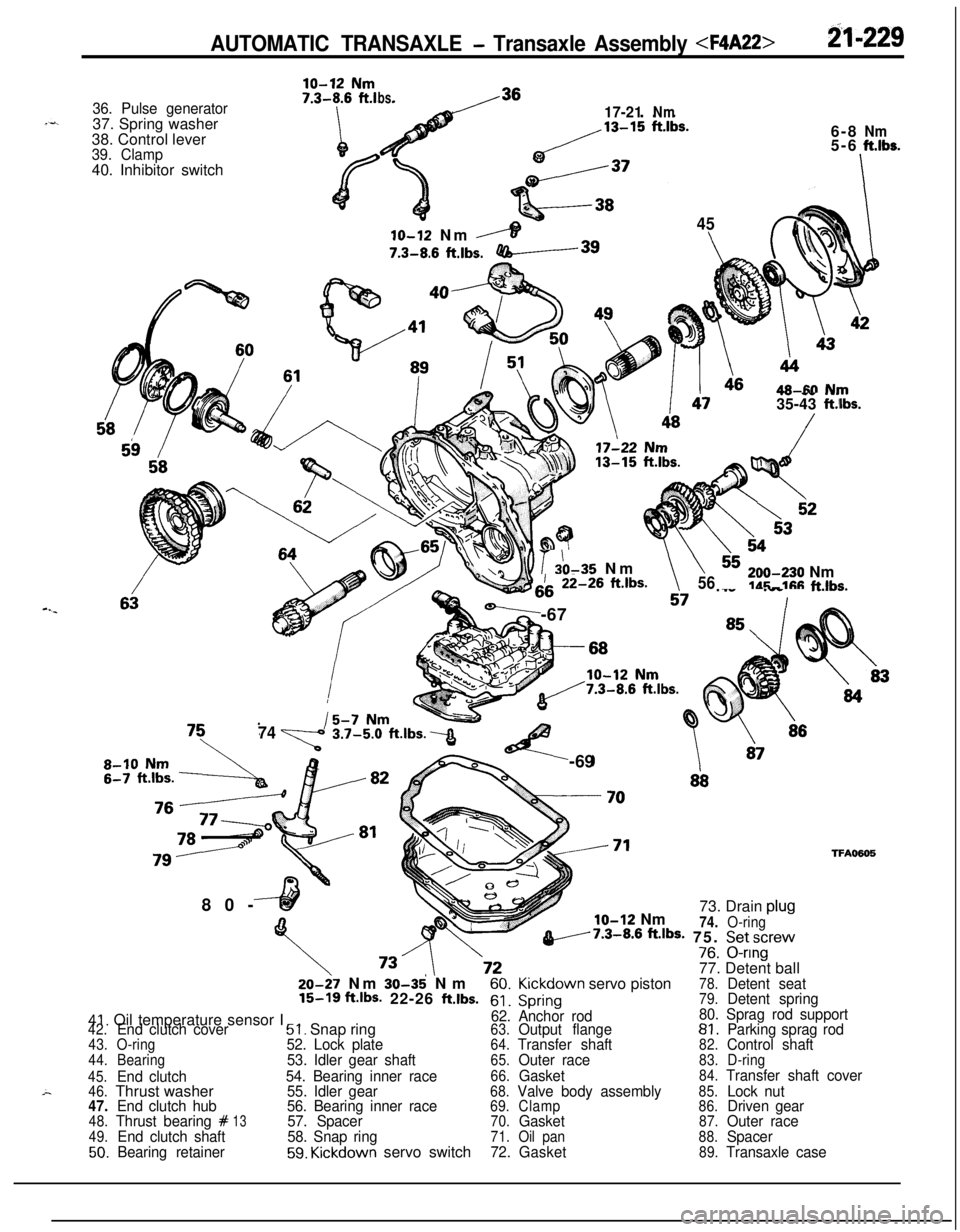
AUTOMATIC TRANSAXLE - Transaxle Assembly B-229
36. Pulse generator37. Spring washer
38. Control lever
39. Clamp40. Inhibitor switch
ln ~19 Nm
bs.17-21Nm6-8
Nm5-6ft.lbs.
-I
45
6IO-12 Nm
,----IT7.3-8.6
ftlbs.-3980-
46AR-M N~JTV -- .-.35-43 ft.iIbs.
b??io r 20-35 Nm\h\\iii-26 ft.lbs.
-,i7 ._.. .__ ._..v.-6756,,,-e30 Nmldr;-11% f-klhs.
I
,
747%!%t.lbs.3<-69
glo-12 Nm73. Drain plu!
74.O-ringv7.3-8.6 ftJbS- 75. Setscrev-^^V/8. u-nng
77. Detent ball
TFA050520-27 Nm
30-35' Nm60.Kickdown servo piston78.Detent seat15-16 ft.lbs- 22-26 ftlbs.61.Spring79.Detent spring
41. Oil temperature sensor I62. Anchor rod80. Sprag rod support42.End clutch cover51. Snap ring63.Output flange81.Parking sprag rod43.O-ring52. Lock plate64.Transfer shaft82.Control shaft44.Bearing53. Idler gear shaft65.Outer race83.D-ring
45.
End clutch54. Bearing inner race66.Gasket84.Transfer shaft cover
46.Thrust washer55. Idler gear68.Valve body assembly85.Lock nut47.End clutch hub56. Bearing inner race69.Clamp86.Driven gear48.Thrust bearing #1357. Spacer70.Gasket87.Outer race49.End clutch shaft58. Snap ring71.Oil pan88.Spacer50.Bearing retainer59. Kickdown servo switch72.Gasket89.Transaxle case
Page 930 of 1216
21-236AUTOMATIC TRANSAXLE - Transaxle Assembly 75017434. Remove planet carrier assembly and thrust bearing
#12.
6,
9-s35. Remove the wave spring, return spring, reaction plate,
brake discs, and brake plates.
36. Since screw lock paste is coated on the screw threads, tap
the screw head for easier removal.
37. Using an impact driver, loosen the screw.
If an impact driver is not available, use a punch or
something similar.
Page 931 of 1216
AUTOMATIC TRANSAXLE - Transaxle Asscimblv 21-23738. Remove idler shaft lock plate.
39. Loosen transfer idler shaft with special tool.
40. Pull out transfer idler shaft. Remove transfer idle gear
bearing inner races (2 pieces) from inside of case.
41. Remove the spacer.
42. Remove snap ring from bearing.
Page 932 of 1216
21-238AUTOMATIC TRANSAXLE - Transaxle Assemblv
43. Remove internal gear, output flange, transfer drive gear andbearing as assembly from case.
*Transfer shaft cover
TFAOMSI44. Remove the transfer shaft cover
45. Stand the transfer shaft lock nut rotation stopper up.
46. Fix the transfer shaft converter housing side.
47. Remove the locking nut.
NOTEThe lock nut is left-hand threaded.
Page 938 of 1216
21-244AUTOMATIC TRANSAXLE - Transaxle Assembly 12. After removing the special tool, affix the converter housing
side of the transfer shaft.
P-13. Tighten the lock nut to the specified torque.
Transfer lock nut:
200-230 Nm (145-166 ft.lbs.)
14. Measure the transfer shaft end play and select and reinstallthe spacer which provides the specified end play.
Transfer shaft end play: O-0.025 mm (O-.0010 in.)
e15. Using a punch, lock the lock nut to prevent rotation.
Attach the transfer cover.
16.
Insert an assembly of the annular gear, output flange,
transfer drive gear and bearing into the case.
Page 940 of 1216
-T1;;z2)6AUTOMATIC TRANSAXLE - Transaxle Assembly 22. Tighten the idler shaft by using special tool.
23. Insert special tool into output flange and measure preload
using a low reading torque wrench.
Adjust preload by tightening or loosening transfer idler
shaft.Preload: 0.6 Nm (0.6
ft.lbs.)24. After the preload adjustment is completed, eliminate the
backlash between the idler shaft and the lock plate by
moving the idler shaft in the loosening direction. Attach the
lock plate and tighten the lock plate bolt.
Lock plate bolt
: 48-60 Nm (35-43 ft.lbs.)25. Install bearing retainer, and tighten screws to specified
torque, apply a 5 mm
(.2 in.) width of sealant (3M Stud
Locking No. 4176) the top. Sealant should not stick out of
screw head.
Screw: 17-22 Nm (13-15
ft.lbs.)head screw to prevent
26. Using a punch, lock the flush
rotation.
Page 960 of 1216

21-266 AUTOMATIC TRANSAXLE -Transaxle Assembly TRANSAXLE ASSEMBLY
DISASSEMBLY AND REASSEMBLY
20.Pressure pla?e21.Brake disc22.Brake plate23.Reaction plate
24. Reverse sun gear25. Thrust bearing
#826. Thrust race
#9---
1.Torque converter2.Oil pump assembly3.Gasket4.Thrust washer #I5. Front clutch assembly
6. Thrust race #37. Thrust bearing #48. Thrust washer #227. l-or-ward sun gear
9. Rear clutch assembly28. Planetary carrier assembly
10. Thrust bearing #529.Thrust bearing#I0
11. Rear clutch hub30.Output flange
12. Thrust race
#631. Oil level gauge
13. Thrust bearing #732. Oil filler tube14.Kickdownband33.
Snap ring15.Kickdowndrum34. Kickdown servo switch16.Snap ring35.Snap ring
Ii524
23
TFA0405’36.
Kickdown servo piston
37.Spring
38.Anchor rod
39.Detent assembly40. Manual control shaft
41. Parking roller support
42.Oilpan43.Gasket44. Oil temperature sensor
45.Oil screen
46. Valve body assembly
47. Manual control lever
48.Inhibitor switch49. End clutch shaft50.Bearing retainer51.Thrust bearing #I152. End clutch hub53.Thrust washer
54. End clutch assembly
55.O-ring
56. End clutch cover
57.Pulse generator58:Lock bolt59.Idler shaft60.Idlergear61.Spacer
62.Gasket