Page 756 of 1216
21-62MANUAL TRANSAXLE - Shift Rails and Forks
SHIFT RAILS AND FORKS
DISASSEMBLY AND REASSEMBLY
N21-
sbdisassembly steps
1, 1 st-2nd speed shift fork2. 1 st-2nd speed shift rail3. 3rd-4th speed shift fork
4. 5th-reverse speed shift rail** 5. Interlock plunger6.
3rd-4th speed shift rail
7. Reverse shift lug
NOTE(1)Reverse the disassembly procedures to reassemble.(2)l *: Refer to “Service Points of Reassembly”.
201073
InterlockReverse shift lugSERVICE POINTS OF REASSEMBLY
5. INSTALLATION OF INTERLOCK PLUNGERinsert the interlock plunger at illustrated position of the
3rd4th speed shift rail.
“r
3rd-4th speed shift rail2ojoaa
Page 757 of 1216
MANUAL TRANSAXLE 4WD> - Differential Assembly21-63
DIFFERENTIAL ASSEMBLYNZlMMAF.
DISASSEMBLY AND REASSEMBLYDisassembly steps
l
+ 1. Bolt2. Differential drive gear
l l a3. Taper roller bearing
+e l +4. Lock pin
M 5. Pinion shaft
l 6. Pinion
e+ 7. Washer
l + 8. Sidegear
l +9. Spacer (Select)10. Differential case
130-440 Nm94- 101 ft.lbs.
\6
NOTE(1) Reverse the disassembly procedures to reassemble.(2) ~~ : Refer to “Service Points of Disassembly”.
(3) ,+ : Refer to “Service Points of Reassembly”.
(4) p : Non-reusable parts
163025
Press
F+ Bearing
SERVICE POINTS OF DISASSEMBLY
3. REMOVAL OF TAPER ROLLER BEARING
Remove the taper roller bearing using the special tool as
illustrated.
Caution ’1. Do not reuse the bearing removed from the dif-
ferential case.
2.Replace the inner and outer races of the taper roller
bearing as a set.
Page 758 of 1216

21-64MANUAL TRANSAXLE - Differential Assembly2150020
Lock pin
Llla
Lock pinDifferen-tial case
alla-ctiol
ock pinendwith2150021
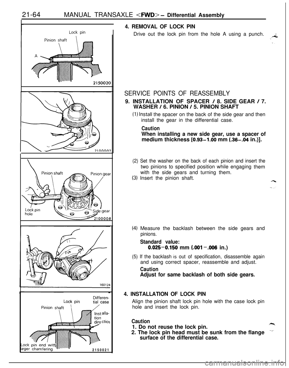
4. REMOVAL OF LOCK PINDrive out the lock pin from the hole A using a punch.
SERVICE POINTS OF REASSEMBLY9. INSTALLATION OF SPACER
/ 8. SIDE GEAR / 7.
WASHER
/ 6. PINION / 5. PINION SHAFT
(1) Install the spacer on the back of the side gear and then
install the gear in the differential case.
Caution
When installing a new side gear, use a spacer ofmedium thickness [0.93-1.00 mm (.36-.04 in.)].
(2) Set the washer on the back of each pinion and insert thetwo pinions to specified position while engaging
them
with the side gears and turning them.
(3) Insert the pinion shaft.
(4) Measure the backlash between the side gears and
pinions.
Standard value:0.025-0.150 mm
LOO1 -.006 in.)
(5) If the backlash is out of specification, disassemble againand using correct spacer, reassemble and adjust.
Caution
Adjust for same backlash of both side gears.
4. INSTALLATION OF LOCK PINAlign the pinion shaft lock pin hole with the case lock pin
hole and insert the lock pin.
Caution1. Do not reuse the lock pin.
2. The lock pin head must be sunk from the flange
surface of the differential case.
Page 760 of 1216
21-66MANUAL TRANSAXLE - Clutch Housing Assembly
CLUTCH HOUSING ASSEMBLYNZlMPAL
DISASSEMBLY AND REASSEMBLY
2=
-,_
1
L--15-22 Nm
11-15 ftlbs.
20-27 Nm15-19 ft.lbs.
Disassembly steps
1.Bolt2. Select lever assembly
3. Select lever shoe
4. Interlock place bolt
5.Gasket+e l *6. Lock pinj\l * l *7. Spring pin
8. Neutral return spring
9.Stopper body10.Control finger11.Interlock plate
12. Neutral return spring assembly
13.Control shaft14. Control shaft boot
l 415.Oil seal
2100019
l * 16. Needle bearing
l a 17. Needle bearing;EJ. Fil;tch housing
20: Return spring
21. Stopper plate
22. Spring pin
NOTE(1) Reverse the disassembl procedures to reassemble.(2)~~ : Refer to “Service ornts of Disassembly”.6.(3)l + : Refer to “Service Points of Reassembly”.(4) q : Non-reusable parts
Page 761 of 1216

MANUAL TRANSAXLE - Clutch Housing Assembly
SERVICE POINTS OF DISASSEMBLY
2f-67
MD998019
\
\
- Control
J$p--lever
201082
MD998\�w
-
20108:
Needle bearing’ ’
20601:
Socketwrench
I’ I20108!
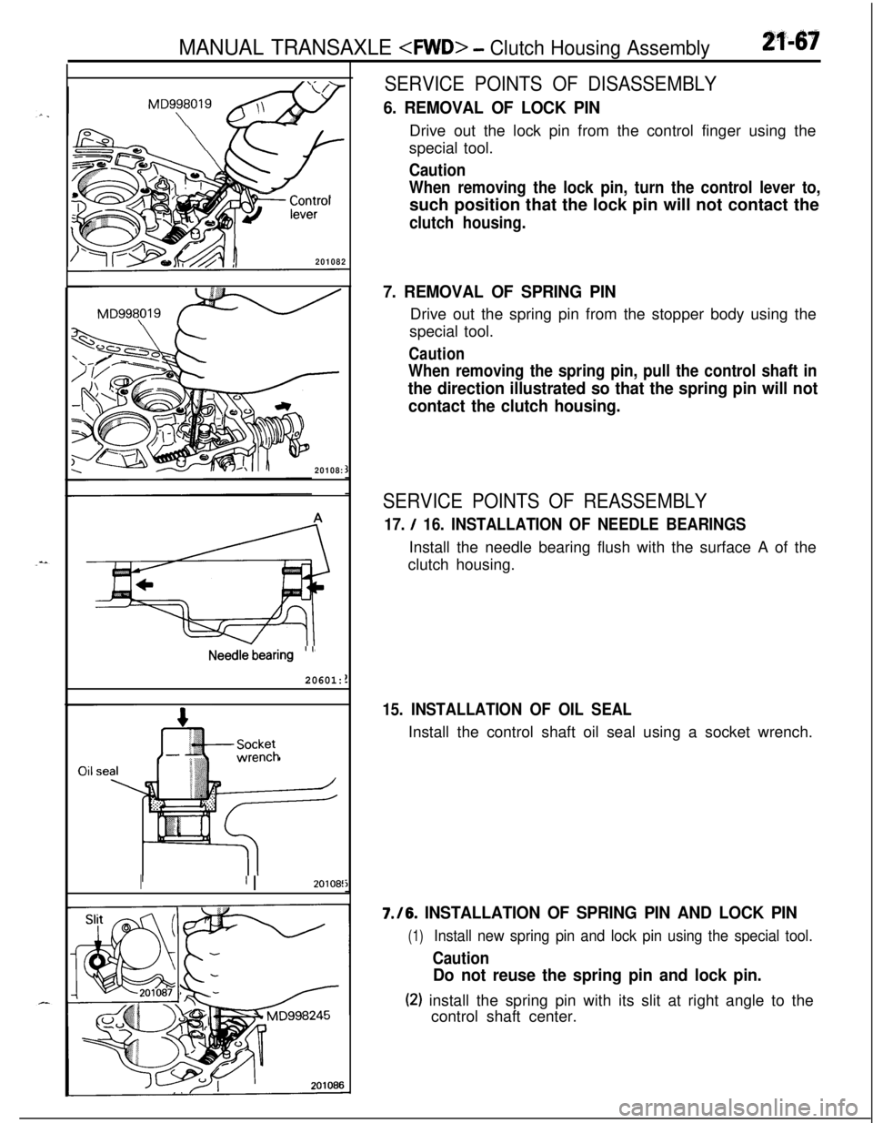
6. REMOVAL OF LOCK PINDrive out the lock pin from the control finger using the
special tool.
Caution
When removing the lock pin, turn the control lever to,such position that the lock pin will not contact the
clutch housing.
7. REMOVAL OF SPRING PINDrive out the spring pin from the stopper body using the
special tool.
Caution
When removing the spring pin, pull the control shaft in
the direction illustrated so that the spring pin will not
contact the clutch housing.
SERVICE POINTS OF REASSEMBLY
17. / 16. INSTALLATION OF NEEDLE BEARINGSInstall the needle bearing flush with the surface A of the
clutch housing.
15. INSTALLATION OF OIL SEALInstall the control shaft oil seal using a socket wrench.7./6.
INSTALLATION OF SPRING PIN AND LOCK PIN
(1)Install new spring pin and lock pin using the special tool.
Caution
Do not reuse the spring pin and lock pin.
(2) install the spring pin with its slit at right angle to the
control shaft center.
Page 769 of 1216

MANUAL TRANSAXLE - Specifications21-75Items
Lower arm ball joint to knuckle
Center bearing bracket installation bolts
Right member installation bolt (front)
Right member installation bolt (rear)
Transfer assembly mounting bolt
Poppet plug
Backup light switch
Restrict ball
Speedometer mounting bolt
Oil filler plug
Oil drain plug
Input shaft lock nut
Intermediate shaft lock nut
Center differential drive gear mounting bolt
Front differential drive gear mounting bolt
Stopper bracket mounting bolt
Reverse idler gear shaft mounting bolt
Reverse shift lever mounting bolt
Bearing retainer mounting bolt
Interlock plate mounting bolt
Center member mounting bolt
Irive shaft center bearing mounting bolt
Iriven bevel lock nutgear
Select lever assembly mounting bolt
3everse brake cone screw boltsNm
ft.Ibs. ”
60-7243-52 “
36-4626-33
80-10058-72
70-8051-58
55-6040-43
30-4222-30
30-3522-25
30-3522-25
3-52.5-3.5
30-3522-25
30-3522-25
140-160102-I 15
140-160102-I 15
70-8051-57
130-14095-10115-22
11-1543-55
32-39
15-22
11-1515-22
11-15
20-2715-19
60-8043-58
36-46
26-33
140-160101-11515-22
11-15
4.0-5.52.9-3.9
TRANSFERItems
Transfer assembly mounting bolt
Cover mounting bolt
Extension housing mounting bolt
Transfer cover mounting bolt
Transfer case adapter mounting bolt
Driven bevel gear lock nut
Hanger bracket mounting boltNm
ft.lbs.
55-6040-43
8-106-7
15-22
II-1535-42
26-3035-42
26-30
140-160102-I 15
15-22
11-15
LUBRICANTSN21CD.BItems
Specified lubricantQuantity lit. (qts.)
I
ITransmission oil
MOPAR Hypoid gear oil or equivalent,2.3 (2.43)
API classification GL-4 or higherITransfer oil
MOPAR Hypoid gear oil or equivalent,
API classification
GL-4 or higher0.6 (.63)
Page 770 of 1216

21-76MANUAL TRANSAXLE -Specifications/Special Tools
SEALANTS AND ADHESIVESNZlCE-B
TransaxleH-
1
-/Items
Transaxle case-clutch housing mating surfaces
Transaxle case-adapter mating surfaces
Adapter-rear cover mating surfaces
Front differential drive gear bolts
Center differential drive gear bolts
Bearing retainer screw (flush head screw)
Reverse brake cone mounting screw bolts
Air breatherSpecified sealants and adhesives
Mitsubishi genuine part
No.997740or equivalent
MOPAR part
No.4318031 or MOPAR part
No. 4318032 or equivalent
MOPAR part
No.4318025 or equivalent
TransferItems
Adapter-extension housing mating surfacesSpecified sealants and adhesives
Mitsubishi genuine part No.
MD997740or equivalent
Air breatherMOPAR part
No.4318025 or equivalent
SPECIAL TOOLSNZlDA-B AI
NllmherName
I Use,“I. .-. * ,--.
~ MD99801 9
.-...-Lock pin extractor---Removal of spring pin and lock pin
MD998245Lock pin installerInstallation of spring pin and lock pin
0
MD998304Oil seal installerInstallation of front output shaft bearing and
transfer extention housing oil seal
MD998320Bearing installer
Installation of input shaft bearing and input
shaft gear
Page 771 of 1216
MANUAL TRANSAXLE - Special Tools21-77Tool
Number
Name
MD998321Oil seal installer
M D998323Bearing installer
MD998325Differential oil seal
installer
MD998350Bearing installer
MD998369Bearing installer
MD998806Wrench adapter
MD998801Bearing remover
MD998802Input shaft holder
M D998803Differential oil seal
installerUse
Installation of input shaft front oil seal
Installation of rear output shaft oil seal and
transfer case oil seal
Installation of differential oil seal
Installation of front output shaft, intermediate
gear, transfer drive bevel gear, and
intermediate gear
Installation of input shaft front bearing
Removal of input shaft, intermediate gear, ant
output shaft bearing and gears
nstallation and removal of input shaft and
Ttermediate gear lock nut
lstallation of differential oil seal
rdjustment of tooth contact and inspection ofJrning drive torquexstallation of input shaft rear snap ring