Page 2018 of 4087
 terminal of the battery.
HINT: Any diagnostic code retained by the computer will be
erased when the battery t")
PRECAUTIONS
1. Before working on the fuel system, disconnect the cablefrom negative (±) terminal of the battery.
HINT: Any diagnostic code retained by the computer will be
erased when the battery terminal is removed. Therefore, if
necessary, read the diagnosis before removing the battery
terminal.
CAUTION: Turn the ignition switch to ºLOCKº. Discon-
nect the cable from the negative (±) terminal of the bat-
tery. Wait at least 20 seconds before proceeding with
work.
2. Do not smoke or work on open flame when working on the fuel system.
3. Keep gasoline away from rubber or leather parts.
INSPECTION PRECAUTIONS
MAINTENANCE PRECAUTIONS
1. CHECK CORRECT ENGINE TUNE±UP (See page EM±8)
2. PRECAUTIONS WHEN CONNECTING GAUGE (a) Use the battery as the power source for the timing light,tachometer, etc.
(b) Connect the test probe of a tachometer to the terminal IG � of the check connector.
3. IN EVENT OF ENGINE MISFIRE, FOLLOWING PRECAUTIONS SHOULD BE TAKEN
(a) Check proper connection of battery terminals, etc.
(b) Handle high±tension cords carefully.
(c) After repair work, check that the ignition coil terminalsand all other ignition system lines are reconnected
securely.
(d) When cleaning the engine compartment, be especially careful to protect the electrical system from water.
4. PRECAUTIONS WHEN HANDLING OXYGEN SENSOR (a) Do not allow oxygen sensor to drop or hit against anobject.
(b) Do not allow the sensor to come into contact with water.
±
EFI SYSTEM Precautions, Inspection PrecautionsFI±11
WhereEverybodyKnowsYourName
Page 2019 of 4087

The ECU has been designed so that it will not be affected by out-
side interference. However, if your vehicle is equipped with a CB
rad")
IF VEHICLE IS EQUIPPED WITH MOBILE
RADIO SYSTEM (HAM, CB, ETC.)
The ECU has been designed so that it will not be affected by out-
side interference. However, if your vehicle is equipped with a CB
radio transceiver, etc. (even one with about 10 W output), it may,
at times, have an effect upon ECU operation, especially if the an-
tenna and feeder are installed nearby.
Therefore, observe the following precautions:
1. Install the antenna as far away as possible from the ECU. The ECU is located on the floor panel on the passenger side
so the antenna should be installed at the rear of the vehicle.
2. Keep the antenna feeder as far away as possible from the ECU wires±at least 20 cm (7.87 in.) ±and, especially, do not
wind them together.
3. Check that the feeder and antenna are properly adjusted.
4. Do not equip your vehicle with a powerful mobile radio
system.
5. Do not open the cover or the case of the ECU unless absolutely necessary. (If the IC terminals are touched, the IC
may be destroyed by static electricity.)
AIR INDUCTION SYSTEM
1. Separation of the engine oil dipstick, oil filler cap, PCV hose,
etc. may cause the engine to run out of tune.
2. Disconnection, looseness or cracks in the parts of the air
induction system between the throttle body and cylinder
head will cause air suction and cause the engine to run out
of tune.
ELECTRONIC CONTROL SYSTEM
1. Before removing EFI wiring connectors, terminals, etc., firstdisconnect the power by either turning the ignition switch
OFF or disconnecting the battery terminals.
HINT: Always check the diagnosis code before disconnecting
the battery terminals.
2. When installing the battery, be especially careful not to
incorrectly connect the positive (+) and negative (±) cables.
3. Do not permit parts to receive a severe impact during removal or installation. Handle all EFI parts carefully, especially the
ECU.
4. Do not be careless during troubleshooting as there are numerous transistor circuits and even slight terminal contact
can cause further troubles.
5. Do not open the ECU cover.
6. When inspecting during rainy weather, take care to prevent entry of water. Also, when washing the engine compartment,
prevent water from getting on the EFI parts and wiring
connectors.
7. Parts should be replaced as an assembly.
FI±12
±
EFI SYSTEM Inspection Precautions
WhereEverybodyKnowsYourName
Page 2023 of 4087
 terminal of the battery.
HINT: Any diagnostic code retained by the computer will be
erased when the battery t")
PRECAUTIONS
1. Before working on the fuel system, disconnect the cablefrom negative (±) terminal of the battery.
HINT: Any diagnostic code retained by the computer will be
erased when the battery terminal is removed. Therefore, if
necessary, read the diagnosis before removing the battery
terminal.
CAUTION: Work must be started after approx. 20 se-
conds or longer from the time the ignition switch is
turned to the ºLOCKº position and negative (±) terminal
cable is disconnected from the battery.
2. Do not smoke or work on open flame when working on the fuel system.
3. Keep gasoline away from rubber or leather parts.
INSPECTION PRECAUTIONS
MAINTENANCE PRECAUTIONS
1. CHECK CORRECT ENGINE TUNE±UP (See page EM±8)
2. PRECAUTIONS WHEN CONNECTING GAUGE (a) Use the battery as the power source for the timing light,tachometer, etc.
(b) Connect the test probe of a tachometer to the terminal IG of the check connector.
3. IN EVENT OF ENGINE MISFIRE, FOLLOWING PRECAUTIONS SHOULD BE TAKEN
(a) Check proper connection of battery terminals, etc.
(b) Handle high±tension cords carefully.
(c) After repair work, check that the ignition coil terminalsand all other ignition system lines are reconnected
securely.
(d) When cleaning the engine compartment, be especially careful to protect the electrical system from water.
4. PRECAUTIONS WHEN HANDLING OXYGEN SENSOR (a) Do not allow oxygen sensor to drop or hit against anobject.
(b) Do not allow the sensor to come into contact with water.
FI±12
± Precautions, Inspection PrecautionsEFI SYSTEM
WhereEverybodyKnowsYourName
Page 2024 of 4087

The ECU has been designed so that it will not be affected by out-
side interference. However, if your vehicle is equipped with a CB
rad")
IF VEHICLE IS EQUIPPED WITH MOBILE
RADIO SYSTEM (HAM, CB, ETC.)
The ECU has been designed so that it will not be affected by out-
side interference. However, if your vehicle is equipped with a CB
radio transceiver, etc. (even one with about 10 W output), it may,
at times, have an effect upon ECU operation, especially if the an-
tenna and feeder are installed nearby.
Therefore, observe the following precautions:
1. Install the antenna as far away as possible from the ECU. The
ECU is located on the floor panel on the passenger side so
the antenna should be installed at the rear of the vehicle.
2. Keep the antenna feeder as far away as possible from the ECU wires±at least 20 cm (7.87 in.)±and, especially, do not
wind them together.
3. Check that the feeder and antenna are properly adjusted.
4. Do not equip your vehicle with a powerful mobile radio
system.
5. Do not open the cover or the case of the ECU unless absolutely necessary. (If the IC terminals are touched, the IC
may be destroyed by static electricity.)
AIR INDUCTION SYSTEM
1. Separation of the engine oil dipstick, oil filler cap, PCV hose,
etc. may cause the engine to run out of tune.
2. Disconnection, looseness or cracks in the parts of the air induction system between the throttle body and cylinder
head will cause air suction and cause the engine to run out
of tune.
ELECTRONIC CONTROL SYSTEM
1. Before removing EFI wiring connectors, terminals, etc., firstdisconnect the power by either turning the ignition switch
OFF or disconnecting the battery terminals.
HINT: Always check the diagnosis code before disconnecting
the battery terminals.
2. When installing the battery, be especially careful not to
incorrectly connect the positive (+) and negative (±) cables.
3. Do not permit parts to receive a severe impact during removal or installation. Handle all EFI parts carefully, especially the
ECU.
4. Do not be careless during troubleshooting as there are numerous transistor circuits and even slight terminal contact
can cause further troubles.
5. Do not open the ECU cover.
6. When inspecting during rainy weather, take care to prevent entry of water. Also, when washing the engine compartment,
prevent water from getting on the EFI parts and wiring
connectors.
7. Parts should be replaced as an assembly. FI±13
EFI SYSTEM
± Inspection Precautions
WhereEverybodyKnowsYourName
Page 2041 of 4087
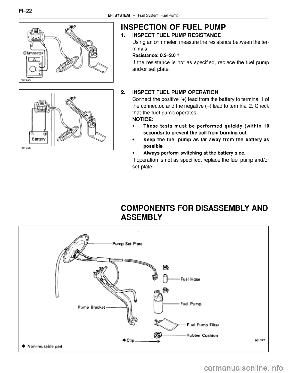
INSPECTION OF FUEL PUMP
1. INSPECT FUEL PUMP RESISTANCEUsing an ohmmeter, measure the resistance between the ter-
minals.
Resistance: 0.2±3.0 �
If the resistance is not as specified, replace the fuel pump
and/or set plate.
2. INSPECT FUEL PUMP OPERATION Connect the positive (+) lead from the battery to terminal 1 of
the connector, and the negative (±) lead to terminal 2. Check
that the fuel pump operates.
NOTICE:
w These tests must be performed quickly (within 10
seconds) to prevent the coil from burning out.
w Keep the fuel pump as far away from the battery as
possible.
w Always perform switching at the battery side.
If operation is not as specified, replace the fuel pump and/or
set plate.
COMPONENTS FOR DISASSEMBLY AND
ASSEMBLY
FI±22EFI SYSTEM ± Fuel System (Fuel Pump)
WhereEverybodyKnowsYourName
Page 2073 of 4087
INSTALLATION OF FUEL PRESSURE
PULSATION DAMPER
(See Components on page FI±35)
1. INSTALL FUEL PRESSURE PULSATION DAMPER (a) In sta ll two ne w ga ske ts, th e No . 1 fu e l pip e an dpulsation damper.
(b) Using SST, torque the pulsation damper.
SST 09612±24014 (09617±24011)
Torque: 41 N Vm (420 kgf Vcm, 30 ft Vlbf)
35 N Vm (350 kgf Vcm, 25 ft Vlbf) for SST
HINT: Use a torque wrench with a fulcrum length of 30 cm
(11.81 in.).
2. INSTALL STARTER (See page ST±5)
Torque: 39 N Vm (400 kgf Vcm, 29 ft Vlbf)
3. (A/T)
INSTALL DIPSTICK GUIDE FOR TRANSMISSION
(a) Install a new O±ring to the dipstick guide.
(b) Apply soapy water to the O±ring.
(c) Connect the dipstick guide end to the tube of the oil pan,
and install the dipstick guide with the bolt.
(d) Install the dipstick.
4. CHECK FOR FUEL LEAKS (See page FI±15)
FI±36
±
EFI SYSTEM Fuel System (Fuel Pressure Pulsation Damper)
WhereEverybodyKnowsYourName
Page 2090 of 4087
PRECAUTIONS
1. Do not leave the ignition switch on for more than 10minutes if the engine will not start.
2. With a tachometer connected to the system, connect the tester probe of the tachometer to terminal IG
of the
check (ºDIAGNOSISº) connector.
HINT:
wAllow the engine to warm up to normal operation
temperature.
w Set the tachometer to the 4±cylinder range.
3. As some tachometers are not compatible with this ignition system, we recommend that you confirm the
compatibility of your unit before use.
4. Never allow the tachometer terminal to touch ground as this could damage the igniter and/or ignition coil.
5. Do not disconnect the battery when the engine is running.
6. Check that the igniter is properly grounded to the body.
±
IGNITION SYSTEM PrecautionsIG±3
WhereEverybodyKnowsYourName
Page 2093 of 4087
ON±VEHICLE INSPECTION
SPARK TEST
CHECK THAT SPARK OCCURS(a) Remove the No.3 timing belt covers.(See steps 2 to 8 on pages IG±11 to 13)
(b) Disconnect the high±tension cords (from the ignition
coils) from the distributor caps.
(c) Hold the end about 12.5 mm (0.50 in.) from the body ground.
(d) Check if spark occurs while engine is being cranked.
HINT: To prevent gasoline from being injected from injectors
during this test, crank the engine for no more than 1±2 se-
conds at a time.
If the spark does not occur, perform the test as follows:
(e) Reconnect the high±tension cords to the distributor caps.
(f) Reinstall the No.3 timing belt covers. (See steps 5 to 11 on pages IG±17 to 19)
IG±6
±
IGNITION SYSTEM On±Vehicle Inspection
WhereEverybodyKnowsYourName

1. INSTALL FUEL PRESSURE PULSATION DAMPER (a) In sta ll two ne w ga ske ts, th e No . 1 fu e l pip e an dpulsation da")

 Remove the No.3 timing belt covers.(See steps 2 to 8 on pages IG±11 to 13)
(b) Disconnect the high±tension cords (from the ignition")