1991 LEXUS SC400 audio
[x] Cancel search: audioPage 12 of 4087

When the negative (±) terminal cable is disconnected from
the battery, memory of the clock and audio systems will be
cancelled. So before starting work, make a record of the con-
tents memorized by each memory system. Then when work
is finished, reset the clock and audio systems as before.
When the vehicle has power tilt and power telescopic steer-
ing, power seat, power outside rear view mirror and power
shoulder belt anchorage, which are all equipped with
memory function, it is not possible to make a record of the
memory contents. So when the operation is finished, it will be
necessary to explain this fact to the customer, and ask the
customer to adjust the features and reset the memory.
To avoid erasing the memory of each memory system, never
use a back±up power supply from outside the vehicle.
3. Even in cases of a minor collision where the airbag does not deploy, the front airbag sensors and the steering wheel pad
should be inspected. (See page AB±9)
4. Never use airbag parts from another vehicle. When replacing parts, replace them with new parts.
5. Before repairs, remove the airbag sensors if shocks are likely
to be applied to the sensors during repairs.
6. The center airbag sensor assembly contains mercury. After
performing replacement, do not destroy the old part. When
scrapping the vehicle or replacing the center airbag sensor
assembly itself, remove the center airbag sensor assembly
and dispose of it as toxic waste.
7. Never disassemble and repair the front airbag sensors, center airbag sensor assembly or steering wheel pad in order
to reuse it.
8. If the front airbag sensors, center airbag sensor assembly or steering wheel pad have been dropped, or if there are cracks,
dents or other defects in the case, bracket or connector,
replace them with new ones.
9. Do not expose the front airbag sensors, center airbag sensor assembly or steering wheel pad directly to hot air or flames.
10. U s e a v o l t / o h m m e t e r w i t h h i g h i m pedance (10 kW/V
minimum) for troubleshooting of the electrical circuit.
11. Information labels are attached to the periphery of the airbag components. Follow the notices.
12. After work on the airbag system is completed, perform the
airbag warning light check (See page AB±30).
±
INTRODUCTION Precautions for Vehicles Equipped with SRS AirbagIN±9
WhereEverybodyKnowsYourName
Page 216 of 4087

GENERAL DESCRIPTION
The LEXUS SC400 is equipped with an SRS (Supplemental Restraint System) a\
irbag.
Failure to carry out service operations in the correct sequence could cause the\
airbag system to unex-
pectedly deploy during servicing, possibly leading to a serious accident.
Further, if a mistake is made in servicing the airbag system, it is possible the\
airbag may fail to operate
when required.
Before performing servicing (including removal or installation of parts, insp\
ection or replacement), be
sure to read the following items carefully, then follow the correct procedure described in the repair
manual.
1. Malfunction symptoms of the airbag system are difficult to confirm, so the diagnostic codes become themost important source of information when troubleshooting.
When troubleshooting the airbag system, always inspect the diagnostic co\
des before disconnecting the
battery (See page AB±25).
2. Work must be started after approx. 20 seconds or longer from the time the ig\
nition switch is turned to the LOCK position and the negative (±) terminal cable is disconnec\
ted from the battery. (The
airbag system is equipped with a back±up power source so that if work is sta\
rted within 20 seconds
of disconnecting the negative (±) terminal cable of the battery, the airbag may be deployed.)
When the negative (±) terminal cable is disconnected from the battery, memory of the clock and audio sys-
tems will be cancelled. So before starting work, make a record of the conten\
ts memorized by the audio
memory system. Then when work is finished, reset the audio systems as before a\
nd adjust the clock. When
the vehicle has power tilt and power telescopic steering, power seat, power \
outside rear view mirror and
power shoulder belt anchorage, which are all equipped with memory function, it\
is not possible to make
a record of the memory contents. So when the work is finished, it will be\
necessary to explain this fact to
the customer, and ask the customer to adjust the features and reset the memory. To avoid erasing the
memory of each memory system, never use a back±up power supply from outside\
the vehicle.
3. Even in cases of a minor collision where the airbag does not deploy, the front airbag sensors and
the steering wheel pad should be inspected (See page AB±9).
4. Never use airbag parts from another vehicle. When replacing parts, replace them with new parts.
5. Before repairs, remove the airbag sensors if shocks are likely to be applied to the sensors during repairs.
6. Never disassemble and repair the front airbag sensors, center airbag sensor a\
ssembly or steering
wheel pad in order to reuse it.
7. If the front airbag sensors, center airbag assembly or steering wheel pa\
d have been dropped, or if there are cracks, dents or other defects in the case, bracket or conn\
ector, replace them with new
ones.
8. Do not expose the front airbag sensors, center airbag sensor assembly or\
steering wheel pad directly to hot air or flames.
9. Use a volt/ohmmeter with high impedance (10 kW/V minimum) for troubleshoo\
ting of the electrical circuit.
10. Information labels are attached to the periphery of the airbag components. Follow t\
he instructions
on the notices.
11. After work on the airbag system is completed, perform the airbag warning\
light check (See page AB±30 ).
AB±2
SRS AIRBAG
± General Description
WhereEverybodyKnowsYourName
Page 246 of 4087
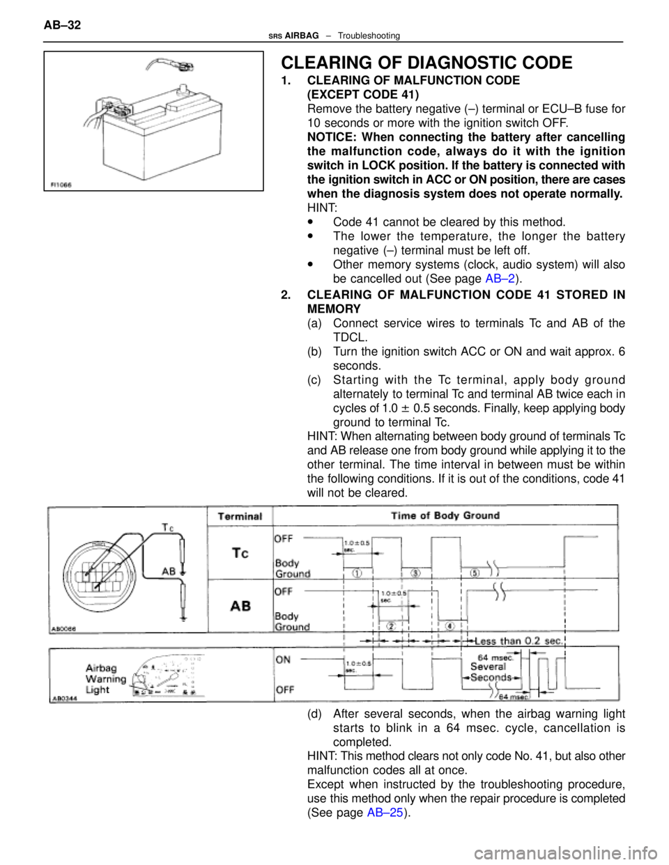
CLEARING OF DIAGNOSTIC CODE
1. CLEARING OF MALFUNCTION CODE(EXCEPT CODE 41)
Remove the battery negative (±) terminal or ECU±B fuse for
10 seconds or more with the ignition switch OFF.
NOTICE: When connecting the battery after cancelling
the malfunction code, always do it with the ignition
switch in LOCK position. If the battery is connected with
the ignition switch in ACC or ON position, there are cases
when the diagnosis system does not operate normally.
HINT:
wCode 41 cannot be cleared by this method.
wThe lower the temperature, the longer the battery
negative (±) terminal must be left off.
wOther memory systems (clock, audio system) will also
be cancelled out (See page AB±2).
2. CLEARING OF MALFUNCTION CODE 41 STORED IN MEMORY
(a) Connect service wires to terminals Tc and AB of theTDCL.
(b) Turn the ignition switch ACC or ON and wait approx. 6 seconds.
(c) S ta rtin g with th e Tc te rmin a l, ap p ly bo d y gr ound
alternately to terminal Tc and terminal AB twice each in
cycles of 1.0 ± 0.5 seconds. Finally, keep applying body
ground to terminal Tc.
HINT: When alternating between body ground of terminals Tc
and AB release one from body ground while applying it to the
other terminal. The time interval in between must be within
the following conditions. If it is out of the conditions, code 41
will not be cleared.
(d) After several seconds, when the airbag warning light
starts to blink in a 64 msec. cycle, cancellation is
completed.
HINT: This method clears not only code No. 41, but also other
malfunction codes all at once.
Except when instructed by the troubleshooting procedure,
use this method only when the repair procedure is completed
(See page AB±25).
AB±32
SRS AIRBAG
± Troubleshooting
WhereEverybodyKnowsYourName
Page 582 of 4087
AUDIO SYSTEM
System Description
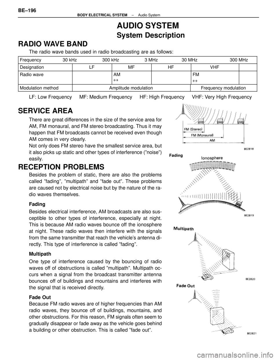
RADIO WAVE BAND
The radio wave bands used in radio broadcasting are as follows:
Frequency 30 kHz300 kHz 3 MHz30 MHz300 MHz
DesignationLFMFHFVHF
Radio waveAM
eFM
e
Modulation methodAmplitude modulationFrequency modulation
LF: Low Frequency MF: Medium Frequency HF: High Frequency VH\
F: Very High Frequency
SERVICE AREA
There are great differences in the size of the service area for
AM, FM monaural, and FM stereo broadcasting. Thus it may
happen that FM broadcasts cannot be received even though
AM comes in very clearly.
Not only does FM stereo have the smallest service area, but
it also picks up static and other types of interference (ºnoiseº)
easily.
RECEPTION PROBLEMS
Besides the problem of static, there are also the problems
called ºfadingº, ºmultipathº and ºfade outº. These pro\
blems
are caused not by electrical noise but by the nature of the ra-
dio waves themselves.
Fading
Besides electrical interference, AM broadcasts are also sus-
ceptible to other types of interference, especially at night.
This is because AM radio waves bounce off the ionosphere
at night. These radio waves then interfere with the signals
from the same transmitter that reach the vehicle's antenna di-
rectly. This type of interference is called ºfadingº.
Multipath
One type of interference caused by the bouncing of radio
waves off of obstructions is called ºmultipathº. Multipath oc-
curs when a signal from the broadcast transmitter antenna
bounces off of buildings and mountains and interferes with
the signal that is received directly.
Fade Out
Because FM radio waves are of higher frequencies than AM
radio waves, they bounce off of buildings, mountains, and
other obstructions. For this reason, FM si gnals often seem to
gradually disappear or fade away as the vehicle goes behind
a building or other obstruction. This is called ºfade outº.
BE±196
±
BODY ELECTRICAL SYSTEM Audio System
WhereEverybodyKnowsYourName
Page 583 of 4087

MAINTENANCE OF TAPE PLAYER
Head Cleaning
Using a moist±type cleaning tape, clean the head surface, pinch rolle\
rs and capstans.
COMPACT DISC PLAYER
Compact Disc (hereafter called ºCDº) players use a laser beam pick±up\
to read the digital signals recorded
on the CD and reproduce analog signals of the music, etc. There are 4.7 in\
. (12 cm) and 3.2 in. (8 cm) CD
available, but it is recommended that you do not use 3.2 in. (8 cm) discs in the\
CD auto changer.
HINT: Never attempt to disassemble or oil any part of the player unit. Do not\
insert any object other than
a disc into the magagine.
NOTICE: CD players use on invisible laser laser beam which could cause hazardou\
s radiation expo-
sure. Be sure to operate the player correctly as instructed.
±
BODY ELECTRICAL SYSTEM Audio SystemBE±197
WhereEverybodyKnowsYourName
Page 584 of 4087
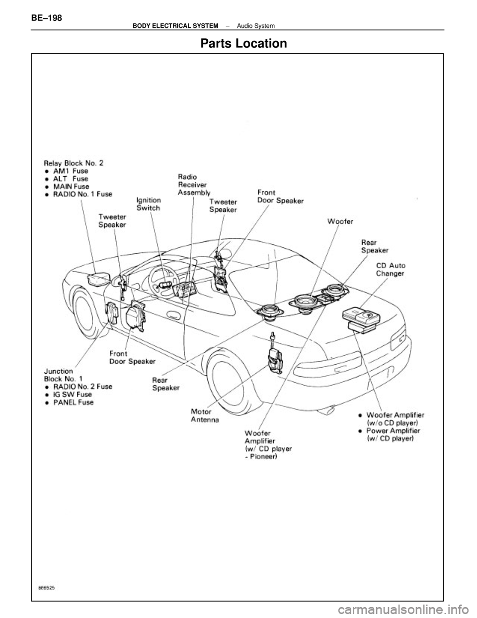
Parts Location
BE±198±
BODY ELECTRICAL SYSTEM Audio System
WhereEverybodyKnowsYourName
Page 585 of 4087
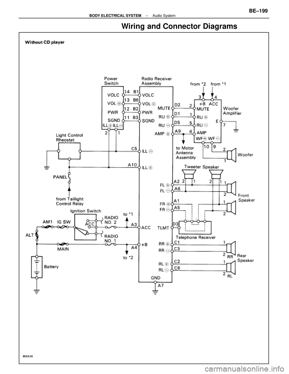
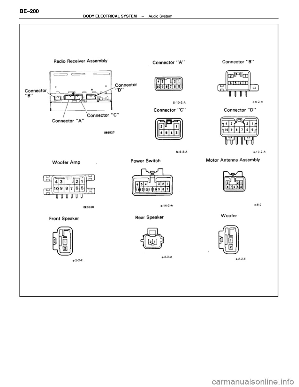
Wiring and Connector Diagrams
±
BODY ELECTRICAL SYSTEM Audio SystemBE±199
WhereEverybodyKnowsYourName
Page 586 of 4087
BE±200±
BODY ELECTRICAL SYSTEM Audio System
WhereEverybodyKnowsYourName