Page 1752 of 4087
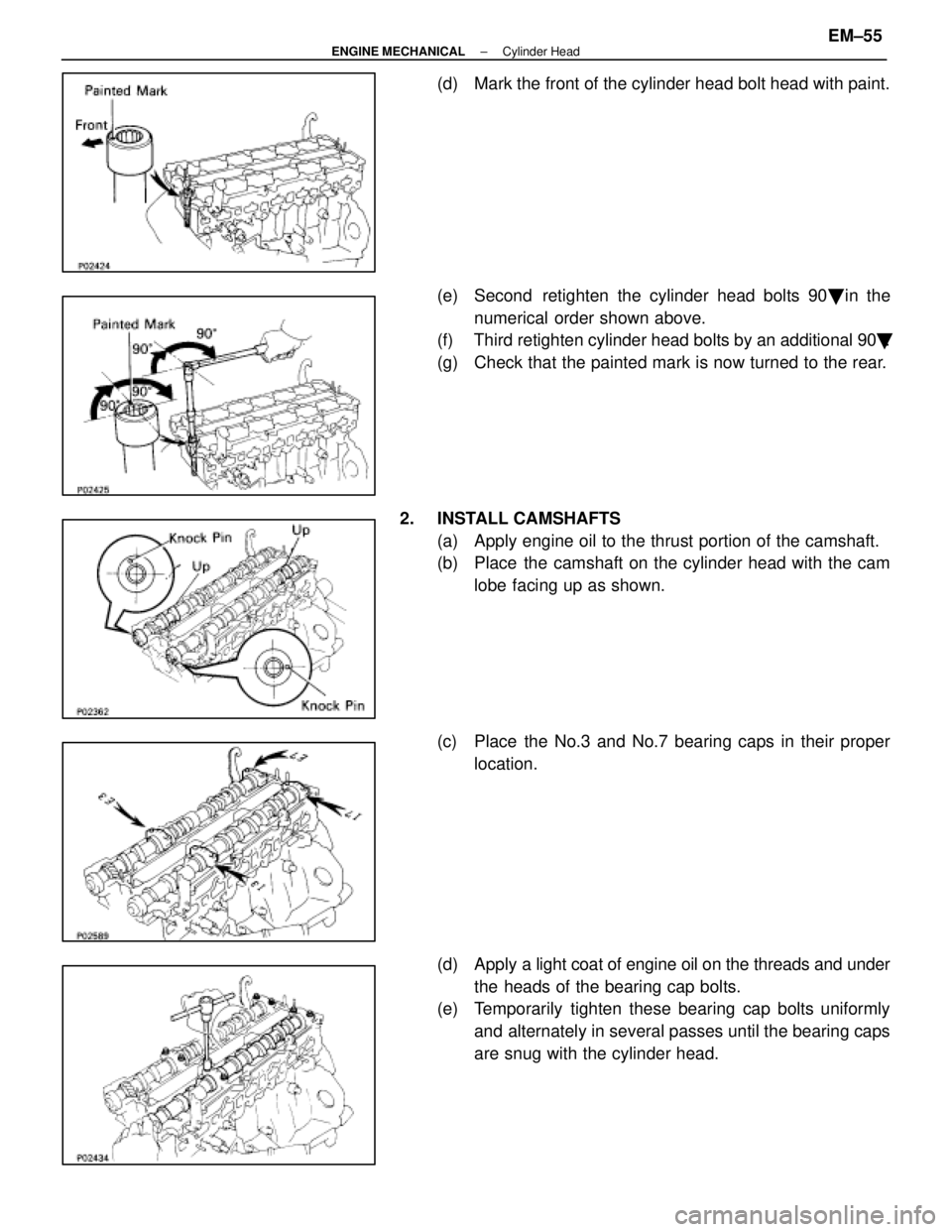
(d) Mark the front of the cylinder head bolt head with paint.
(e) Second retighten the cylinder head bolts 90� in the
numerical order shown above.
(f) Third retighten cylinder head bolts by an additional 90 �.
(g) Check that the painted mark is now turned to the rear.
2. INSTALL CAMSHAFTS (a) Apply engine oil to the thrust portion of the camshaft.
(b) Place the camshaft on the cylinder head with the camlobe facing up as shown.
(c) Place the No.3 and No.7 bearing caps in their proper location.
(d) Apply a light coat of engine oil on the threads and under
the heads of the bearing cap bolts.
(e) Temporarily tighten these bearing cap bolts uniformly
and alternately in several passes until the bearing caps
are snug with the cylinder head.
±
ENGINE MECHANICAL Cylinder HeadEM±55
WhereEverybodyKnowsYourName
Page 1754 of 4087
 Using SST, push the oil seal as far as it would go.
SST 09316±60010 (09316±00010, 09316±00050)
(n) Rotate the camshaft with a wrench at the hexagonposition, bring the forward straight pin u")
(m) Using SST, push the oil seal as far as it would go.
SST 09316±60010 (09316±00010, 09316±00050)
(n) Rotate the camshaft with a wrench at the hexagonposition, bring the forward straight pin up.
(o) Loosen the two bearing cap bolts as shown, until they
can be turned by hand; retighten in several passes.
Torque: 20 N Vm (200 kgf Vcm, 14 ft Vlbf)
(p) Turn the camshaft 1/3 of revolution.
(q) Loosen the two bearing cap bolts as shown, until they
can be turned by hand; retighten in several passes.
Torque: 20 N Vm (200 kgf Vcm, 14 ft Vlbf)
(r) Turn the camshaft a further 1/3 of a revolution.
(s) Loosen the two bearing cap bolts as shown, until they
can be turned by hand; retighten is several passes.
Torque: 20 N Vm (200 kgf Vcm, 14 ft Vlbf)
3. CHECK AND ADJUST VALVE CLEARANCE
(See steps 12 and 13 on pages EM±12 to 16)
Turn the camshaft, and position the cam lobe upward, check
and adjust the valve clearance.
Valve clearance:
Intake 0.15±0.25 mm (0.006±0.010 in.)
Exhaust 0.25±0.35 mm (0.010±0.014 in.)
±
ENGINE MECHANICAL Cylinder HeadEM±57
WhereEverybodyKnowsYourName
Page 1756 of 4087
 Install the harness protector to the intake manifold withthe two bolts.
(b) Install the three clamp bolts and two nuts.
(c) Connect the following conn")
8. CONNECT ENGINE WIRE TO INTAKE MANIFOLD(a) Install the harness protector to the intake manifold withthe two bolts.
(b) Install the three clamp bolts and two nuts.
(c) Connect the following connectors:
(1) Engine coolant temperature sensor connector
(2) Engine coolant temperature sender gauge connec- tor
(3) Two knock sensor connectors
(4) Oil pressure switch connector
(5) Oil level sensor connector
(6) A/C compressor connector
9. INSTALL NO. 1 AND NO. 2 FUEL PIPES
Torque: 8.8 N Vm (90 kgf Vcm, 78 in. Vlbf)
10. INSTALL DELIVERY PIPE AND INJECTORS
(See steps 1, 3, 6 and 7 on pages FI±33 and 34)
Torque: 21 N Vm (210 kgf Vcm, 15 ft Vlbf)
11. INSTALL AIR INTAKE CHAMBER
(a) Install a new gasket and the intake chamber with the five
bolts and two nuts.
Torque: 21 N Vm (210 kgf Vcm, 15 ft Vlbf)
(b) Install the check connector and harness protector to the
air intake chamber with the two bolts.
(c) Connect the following hoses: (1) Vacuum hose to brake booster union
(2) Vacuum hose (to ACIS vacuum tank)
(3) Vacuum sensing hose
(4) Air hose (to PS air control valve)
±
ENGINE MECHANICAL Cylinder HeadEM±59
WhereEverybodyKnowsYourName
Page 1786 of 4087
 Place the camshaft on V±blocks.
(b) Using a dial indicator, measure the circle runout at thecenter journal.
Maximum circle run")
10. INSPECT CAMSHAFTS AND BEARINGS
A. Inspect camshaft for runout(a) Place the camshaft on V±blocks.
(b) Using a dial indicator, measure the circle runout at thecenter journal.
Maximum circle runout: 0.08 mm (0.0031 in.)
If the circle runout is greater than maximum, replace the cam-
shaft.
B. Inspect cam lobes Using a micrometer, measure the cam lobe height.
Standard cam lobe height:
Intake 41.710±41.810 mm (1.6421±1.6461 in.)
Exhaust 41.910±42.010 mm (1.6500±1.6539 in.)
Minimum cam lobe height: Intake 41.56 mm (1.6362 in.)
Exhaust 41.76 mm (1.6441 in.)
If the cam lobe height is less than minimum, replace the cam-
shaft.
C. Inspect camshaft journals Using a micrometer, measure the journal diameter.
Journal diameter:
Exhaust camshaft thrust portion (A) 23.959±23.975 mm
(0.9433±0.9439 in.)
Others 26.954±26.970 mm (1.0612±1.0618 in.)
If the journal diameter is not as specified, check the oil clear-
ance.
D. Inspect camshaft bearings Check the bearings for flaking and scoring.
If the bearings are damaged, replace the bearing caps and
cylinder head as a set.
±
ENGINE MECHANICAL Cylinder HeadsEM±85
WhereEverybodyKnowsYourName
Page 1791 of 4087
2. INSTALL VALVES(a) Using SST, push in a new oil seal.
SST 09201±41020
(b) Install the following parts:(1) Valve
(2) Spring seat
(3) Valve spring
(4) Spring retainer
(c) Using SST, compress the valve spring and place the two
keepers around the valve stem.
SST 09202±70010
(d) Using a plastic±faced hammer, lightly tap the valve stem
tip to assure proper fit.
3. INSTALL VALVE LIFTERS AND SHIMS Check the valve lifter rotates smoothly by hand.
EM±90
±
ENGINE MECHANICAL Cylinder Heads
WhereEverybodyKnowsYourName
Page 1794 of 4087
 and (e)).
w If any one of the cylinder head bolts broken or deformed,
replace it.
(a) Appl")
B. Install cylinder head boltsHINT:
wThe cylinder head bolts are tighten in two progressive
steps (steps (c) and (e)).
w If any one of the cylinder head bolts broken or deformed,
replace it.
(a) Apply a light coat of engine oil on the threads and under
the heads of the cylinder head bolts.
(b) Te mp o ra rily in sta ll th e twe n ty pla te wa sh e rs an d cylinder head bolts.
(c) Uniformly tighten the ten cylinder head bolts on one side
of the cylinder head in several passes in the sequence
shown, then do the other side as shown.
Torque: 39 N Vm (400 kgf Vcm, 29 ft Vlbf)
If any one of the bolts does not meet the torque specification,
replace the bolt.
(d) Mark the front of the cylinder head bolt head with paint.
(e) Retighten the cylinder head bolts 90 ° in the numerical
order shown.
(f) Check that the painted mark is now at a 90 ° angle to
front.
4. CONNECT MAIN OXYGEN SENSOR CONNECTORS Connect the RH and LH oxygen sensor connector.
5. INSTALL CIRCULAR PLUGS (a) Place two new circular plugs in position on the cylinderheads, facing the cup side forward.
±
ENGINE MECHANICAL Cylinder HeadsEM±93
WhereEverybodyKnowsYourName
Page 1798 of 4087
 Check that the exhaust camshaft moves smoothly in the
thrust direction.
(f) Install the rear bearing cap with the arrow mark facing rearward.
HINT:
w Installing the rear bearing cap will determi")
(e) Check that the exhaust camshaft moves smoothly in the
thrust direction.
(f) Install the rear bearing cap with the arrow mark facing rearward.
HINT:
w Installing the rear bearing cap will determine the thrust
position of the camshaft.
w Align the arrow marks at front and rear of the cylinder
head with the mark on the bearing cap.
(g) Install the other bearing caps in the sequence shown with the arrow mark facing rearward.
HINT: Align the arrow marks at front and rear of the cylinder
head with the mark on the bearing cap.
(h) Apply a light coat of engine oil on the threads and under
the heads of the bearing cap bolts.
(i) Install the oil feed pipe and ten bolts.
HINT: Use bearing cap bolts 38 mm (1.50 in.) and 52 mm
(2.05 in.) in length. Use black colored 38 mm (1.50 in.) bolts.
Install the two 52 mm (2.05 in.) bolts in outside positions of
the oil pipe. Install the eight 38 mm (1.50 in.) bolts in the other
positions.
(j) Uniformly tighten the eight bearing cap bolts on the bearing caps of the exhaust camshaft in several passes
in the sequence shown.
Torque: 16 N Vm (160 kgf Vcm, 12 ft Vlbf)
±
ENGINE MECHANICAL Cylinder HeadsEM±97
WhereEverybodyKnowsYourName
Page 1801 of 4087
 Check that the exhaust camshaft moves smoothly in the
thrust direction.
(f) Install the front bearing cap with the arrow mark facing forward.
HINT:
w Installing the front bearing cap will determ")
(e) Check that the exhaust camshaft moves smoothly in the
thrust direction.
(f) Install the front bearing cap with the arrow mark facing forward.
HINT:
w Installing the front bearing cap will determine the thrust
position of the camshaft.
w Align the arrow marks at front and rear of the cylinder
head with the mark on the bearing cap.
(g) Install the other bearing caps in the sequence shown with the arrow mark facing forward.
HINT: Align the arrow marks at front and rear of the cylinder
head with the mark on the bearing cap.
(h) Apply a light coat of engine oil on the threads and under
the heads of the bearing cap bolts.
(i) Install the oil feed pipe and ten bolts.
HINT: Use bearing cap bolts 38 mm (1.50 in.) and 52 mm
(2.05 in.) in length. Use black colored 38 mm (1.50 in.) bolts.
Install the two 52 mm (2.05 in.) bolts in outside positions of
the oil pipe. Install the eight 38 mm (1.50 in.) bolts in the other
positions.
(j) Uniformly tighten the eight bearing cap bolts on the
bearing caps of the exhaust camshaft in several passes
in the sequence shown.
Torque: 16 N Vm (160 kgf Vcm, 12 ft Vlbf)
EM±100±
ENGINE MECHANICAL Cylinder Heads
WhereEverybodyKnowsYourName
 Using SST, push in a new oil seal.
SST 09201±41020
(b) Install the following parts:(1) Valve
(2) Spring seat
(3) Valve spring
(4) Spring retainer
(c) Using SST, compress the")