Page 1579 of 4087
34. FILL WITH ENGINE COOLANT
35. FILL WITH ENGINE OIL
36. START ENGINE AND CHECK FOR LEAKS
37. CHECK TRANSMISSION FLUID LEVEL
38. PERFORM ENGINE ADJUSTMENT(See Tune±Up on pages EG±9 to 34)
39. INSTALL ENGINE UNDER COVER
40. INSTALL HOOD
41. PERFORM ROAD TEST Check for abnormal noise, shock slippage, correct shift
points and smooth operation.
42. RECHECK ENGINE COOLANT AND OIL LEVELS
±
1UZ±FE ENGINE ENGINE MECHANICALEG±203
WhereEverybodyKnowsYourName
Page 1600 of 4087

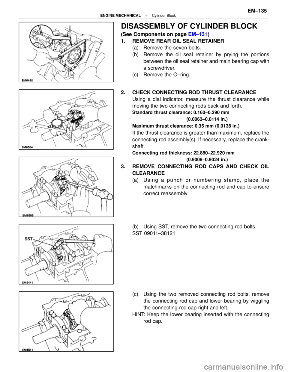
DISASSEMBLY OF CYLINDER BLOCK
(See Components on page EM±131)
1. REMOVE REAR OIL SEAL RETAINER (a) Remove the seven bolts.
(b) Remove the oil seal retainer by prying the portions
between the oil seal retainer and main bearing cap with
a screwdriver.
(c) Remove the O±ring.
2. CHECK CONNECTING ROD THRUST CLEARANCE Using a dial indicator, measure the thrust clearance while
moving the two connecting rods back and forth.
Standard thrust clearance: 0.160±0.290 mm
(0.0063±0.0114 in.)
Maximum thrust clearance: 0.35 mm (0.0138 in.)
If the thrust clearance is greater than maximum, replace the
connecting rod assembly(s). If necessary, replace the crank-
shaft.
Connecting rod thickness: 22.880±22.920 mm (0.9008±0.9024 in.)
3. REMOVE CONNECTING ROD CAPS AND CHECK OILCLEARANCE
(a) Using a punch or numbering stamp, place thematchmarks on the connecting rod and cap to ensure
correct reassembly.
(b) Using SST, remove the two connecting rod bolts.
SST 09011±38121
(c) Using the two removed connecting rod bolts, remove the connecting rod cap and lower bearing by wiggling
the connecting rod cap right and left.
HINT: Keep the lower bearing inserted with the connecting rod cap.
±
ENGINE MECHANICAL Cylinder BlockEM±135
WhereEverybodyKnowsYourName
Page 1603 of 4087
HINT:
wKeep the bearings, connecting rod and cap together.
w Arrange the piston and connecting rod assemblies in
correct order.
5. CHECK CRANKSHAFT THRUST CLEARANCE Using a dial indi cator, measure the thrust clearance while pry-
ing the crankshaft back and forth with a screwdriver.
Standard thrust clearance: 0.020±0.220 mm
(0.0008±0.0087 in.)
Maximum thrust clearance: 0.30 mm (0.0118 in.)
If the thrust clearance is greater than maximum, replace the
thrust washers as a set.
Thrust washer thickness: 2.440±2.490 mm (0.0961±0.0980 in.)
6. REMOVE MAIN BEARING CAP AND CHECK OILCLEARANCE
(a) Remove the ten main bearing cap bolts.
(b) Uniformly loosen and remove the twenty main bearingcap nuts in several passes in the sequence shown.
EM±138
±
ENGINE MECHANICAL Cylinder Block
WhereEverybodyKnowsYourName
Page 1609 of 4087

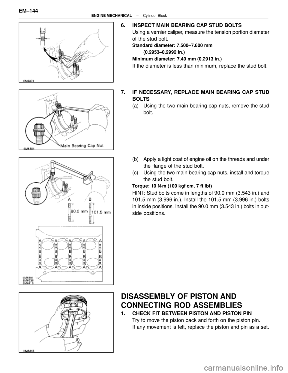
6. INSPECT MAIN BEARING CAP STUD BOLTSUsing a vernier caliper, measure the tension portion diameter
of the stud bolt.
Standard diameter: 7.500±7.600 mm
(0.2953±0.2992 in.)
Minimum diameter: 7.40 mm (0.2913 in.)
If the diameter is less than minimum, replace the stud bolt.
7. IF NECESSARY, REPLACE MAIN BEARING CAP STUD BOLTS
(a) Using the two main bearing cap nuts, remove the studbolt.
(b) Apply a light coat of engine oil on the threads and under
the flange of the stud bolt.
(c) Using the two main bearing cap nuts, install and torque
the stud bolt.
Torque: 10 N Vm (100 kgf Vcm, 7 ft Vlbf)
HINT: Stud bolts come in lengths of 90.0 mm (3.543 in.) and
101.5 mm (3.996 in.). Install the 101.5 mm (3.996 in.) bolts
in inside positions. Install the 90.0 mm (3.543 in.) bolts in out-
side positions.
DISASSEMBLY OF PISTON AND
CONNECTING ROD ASSEMBLIES
1. CHECK FIT BETWEEN PISTON AND PISTON PIN
Try to move the piston back and forth on the piston pin.
If any movement is felt, replace the piston and pin as a set.
EM±144
±
ENGINE MECHANICAL Cylinder Block
WhereEverybodyKnowsYourName
Page 1614 of 4087

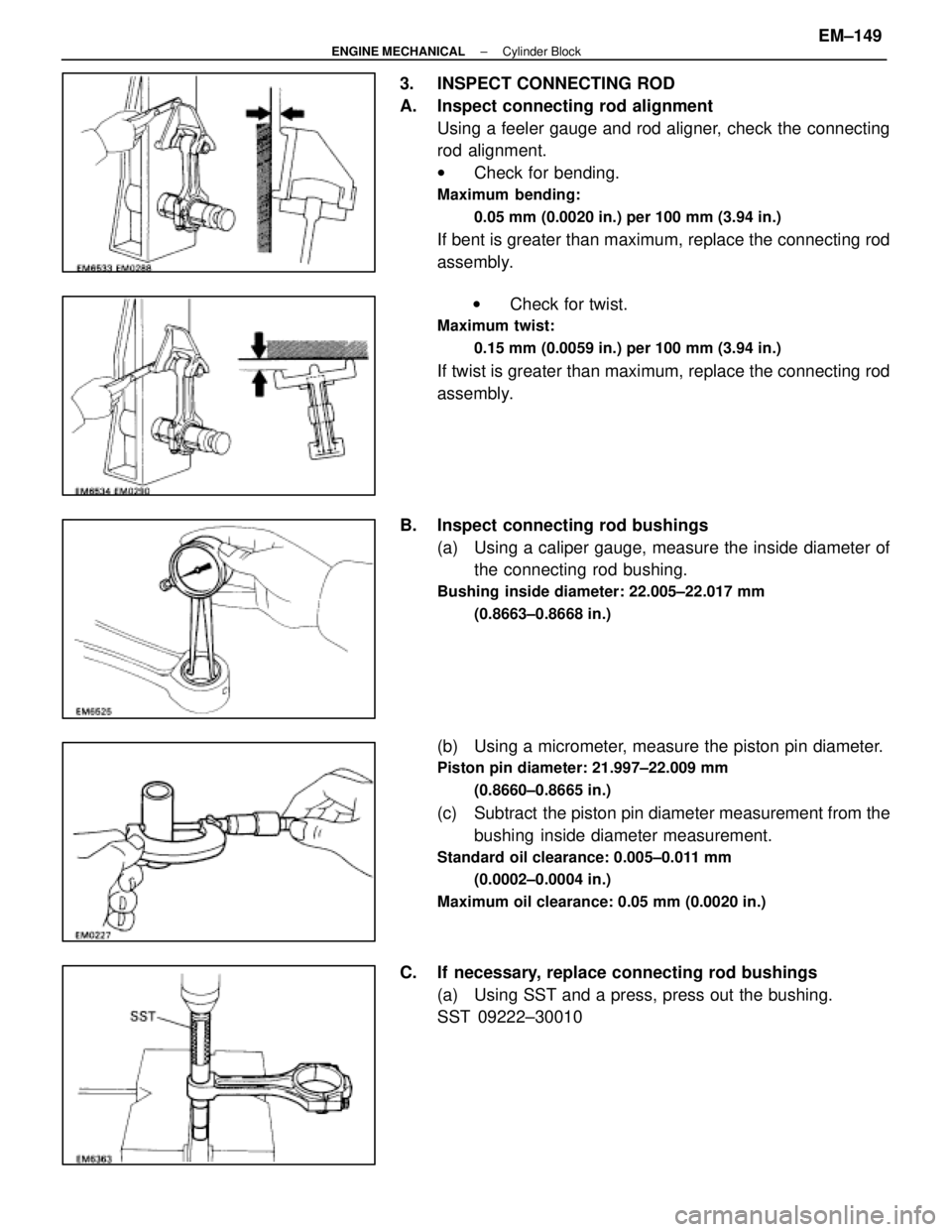
3. INSPECT CONNECTING ROD
A. Inspect connecting rod alignmentUsing a feeler gauge and rod aligner, check the connecting
rod alignment.
wCheck for bending.
Maximum bending:
0.05 mm (0.0020 in.) per 100 mm (3.94 in.)
If bent is greater than maximum, replace the connecting rod
assembly.
w Check for twist.
Maximum twist:
0.15 mm (0.0059 in.) per 100 mm (3.94 in.)
If twist is greater than maximum, replace the connecting rod
assembly.
B. Inspect connecting rod bushings (a) Using a caliper gauge, measure the inside diameter ofthe connecting rod bushing.
Bushing inside diameter: 22.005±22.017 mm
(0.8663±0.8668 in.)
(b) Using a micrometer, measure the piston pin diameter.
Piston pin diameter: 21.997±22.009 mm(0.8660±0.8665 in.)
(c) Subtract the piston pin diameter measurement from thebushing inside diameter measurement.
Standard oil clearance: 0.005±0.011 mm
(0.0002±0.0004 in.)
Maximum oil clearance: 0.05 mm (0.0020 in.)
C. If necessary, replace connecting rod bushings (a) Using SST and a press, press out the bushing.
SST 09222±30010
±
ENGINE MECHANICAL Cylinder BlockEM±149
WhereEverybodyKnowsYourName
Page 1615 of 4087
(b) Align the oil holes of the connecting rod and a newbushing.
(c) Using SST and a press, press in the bushing.
SST 09222±30010
(d) Using a pin hole grinder, hole the bushing to obtain the standard specified clearance (see step B above)
between the bushing and piston pin.
(e) Check the piston pin fit at normal room temperature.
Coat the piston pin with engine oil, and push it into the con-
necting rod with your thumb.
D. Inspect connecting rod bolts Using a vernier caliper, measure the tension portion diameter
of the bolt.
Standard diameter: 7.200±7.300 mm
(0.2835±0.2874 in.)
Minimum diameter: 7.00 mm (0.2756 in.)
If the outside diameter is less than minimum, replace the bolt.
EM±150
±
ENGINE MECHANICAL Cylinder Block
WhereEverybodyKnowsYourName
Page 1616 of 4087
INSPECTION OF CRANKSHAFT
1. INSPECT CRANKSHAFT FOR RUNOUT(a) Place the crankshaft on V±blocks.
(b) Using a dial indicator, measure the circle runout at thecenter journal.
Maximum circle runout: 0.08 mm (0.0031 in.)
If the circle runout is greater than maximum, replace the
crankshaft.
2. INSPECT MAIN JOURNALS AND CRANK PINS (a) Using a micr ometer, measure the diameter of each main
journal and crank pin.
Main journal diameter: 66.988±67.000 mm
(2.6373±2.6378 in.)
Crank pin diameter: 51.982±52.000 mm (2.0465±2.0472 in.)
If the diameter is not as specified, check the oil clearance
(See page EM±136 or 139).
(b) Check each main journal and crank pin for taper and out±of±round as shown.
Maximum taper and out±of±round: 0.02 mm
(0.0008 in.)
If the taper or out±of±round is greater than maximum, re-
place the crankshaft.
±
ENGINE MECHANICAL Cylinder BlockEM±151
WhereEverybodyKnowsYourName
Page 1624 of 4087

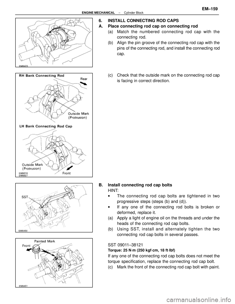
6. INSTALL CONNECTING ROD CAPS
A. Place connecting rod cap on connecting rod(a) Match the numbered c onnecting rod cap with the
connecting rod.
(b) Align the pin groove of the connecting rod cap with the pins of the connecting rod, and install the connecting rod
cap.
(c) Check that the outside mark on the connecting rod cap is facing in correct direction.
B. Install connecting rod cap bolts HINT:
wThe connecting rod cap bolts are tightened in two
progressive steps (steps (b) and (d)).
w If any one of the connecting rod bolts is broken or
deformed, replace it.
(a) Apply a light of engine oil on the threads and under the
heads of the connecting rod cap bolts.
(b) Usin g SS T, in sta ll an d alte rn a te ly tig h te n th e two connecting rod cap bolts in several passes.
SST 09011±38121
Torque: 25 N Vm (250 kgf Vcm, 18 ft Vlbf)
If any one of the connecting rod cap bolts does not meet the
torque specification, replace the connecting rod cap bolt.
(c) Mark the front of the connecting rod cap bolt with paint.
±
ENGINE MECHANICAL Cylinder BlockEM±159
WhereEverybodyKnowsYourName