Page 1713 of 4087
22. REMOVE ALTERNATOR(a) Disconnect the alternator connector.
(b) Remove the cap and nut, and disconnect the alternatorwire.
(c) Remove the bolt, and disconnect the A/T oil cooler pipe bracket.
(d) Remove the nut and alternator.
23. REMOVE DRIVE BELT TENSIONER Remove the bolt, two nuts and tensioner.
24. REMOVE SPARK PLUGS Using a 16 mm plug wrench, remove the eight spark plugs.
25. IF RE±USING TIMING BELT, CHECK INSTALLATION MARKS ON TIMING BELT
Check that there are four installation marks on the timing belt
by turning the crankshaft pulley as shown in the illustration.
If the installation marks have disappeared, place a new
installation mark on the timing belt before removing each
part.
26. SET NO.1 CYLINDER TO TDC/COMPRESSION (a) Turn the crankshaft pulley and align its groove with thetiming mark ºOº of the No.1 timing belt cover.
EM±40
±
ENGINE MECHANICAL Timing Belt
WhereEverybodyKnowsYourName
Page 1717 of 4087
36. REMOVE NO.2 IDLER PULLEYRemove the pulley bolt and idler pulley.
37. REMOVE NO.1 IDLER PULLEY Using a 10 mm hexagon wrench, remove the bolt, idler pulley
and plate washer.
38. REMOVE CRANKSHAFT TIMING PULLEY Using SST, remove the timing pulley.
SST 09213±60017 (09213±00050)
INSPECTION OF TIMING BELT
COMPONENTS
1. INSPECT TIMING BELTNOTICE:
w Do not bend, twist or turn the timing belt inside out.
w Do not allow the timing belt to come into contact with oil,
water or steam.
w Do not utilize timing belt tension when installing or
removing the mounting bolt of the camshaft timing
pulley.
If there are any defects as shown in the illustrations, check
the following points:
(a) Premature parting
w Check for proper installation.
w Check the timing cover gasket for damage and
proper installation.
EM±44
±
ENGINE MECHANICAL Timing Belt
WhereEverybodyKnowsYourName
Page 1719 of 4087
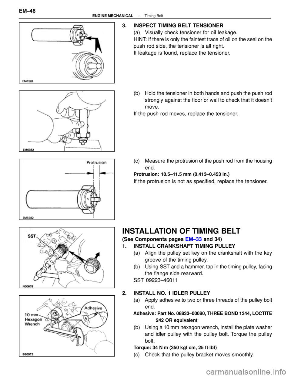
3. INSPECT TIMING BELT TENSIONER(a) Visually check tensioner for oil leakage.
HINT: If there is only the faintest trace of oil on the seal on the
push rod side, the tensioner is all right.
If leakage is found, replace the tensioner.
(b) Hold the tensioner in both hands and push the push rodstrongly against the floor or wall to check that it doesn't
move.
If the push rod moves, replace the tensioner.
(c) Measure the protrusion of the push rod from the housing
end.
Protrusion: 10.5±11.5 mm (0.413±0.453 in.)
If the protrusion is not as specified, replace the tensioner.
INSTALLATION OF TIMING BELT
(See Components pages EM±33 and 34)
1. INSTALL CRANKSHAFT TIMING PULLEY (a) Align the pulley set key on the crankshaft with the keygroove of the timing pulley.
(b) Using SST and a hammer, tap in the timing pulley, facing
the flange side rearward.
SST 09223±46011
2. INSTALL NO. 1 IDLER PULLEY (a) Apply adhesive to two or three threads of the pulley boltend.
Adhesive: Part No. 08833±00080, THREE BOND 1344, LOCTITE
242 OR equivalent
(b) Using a 10 mm hexagon wrench, install the plate washer
and idler pulley with the pulley bolt. Torque the pulley
bolt.
Torque: 34 N Vm (350 kgf Vcm, 25 ft Vlbf)
(c) Check that the pulley bracket moves smoothly.
EM±46
±
ENGINE MECHANICAL Timing Belt
WhereEverybodyKnowsYourName
Page 1720 of 4087
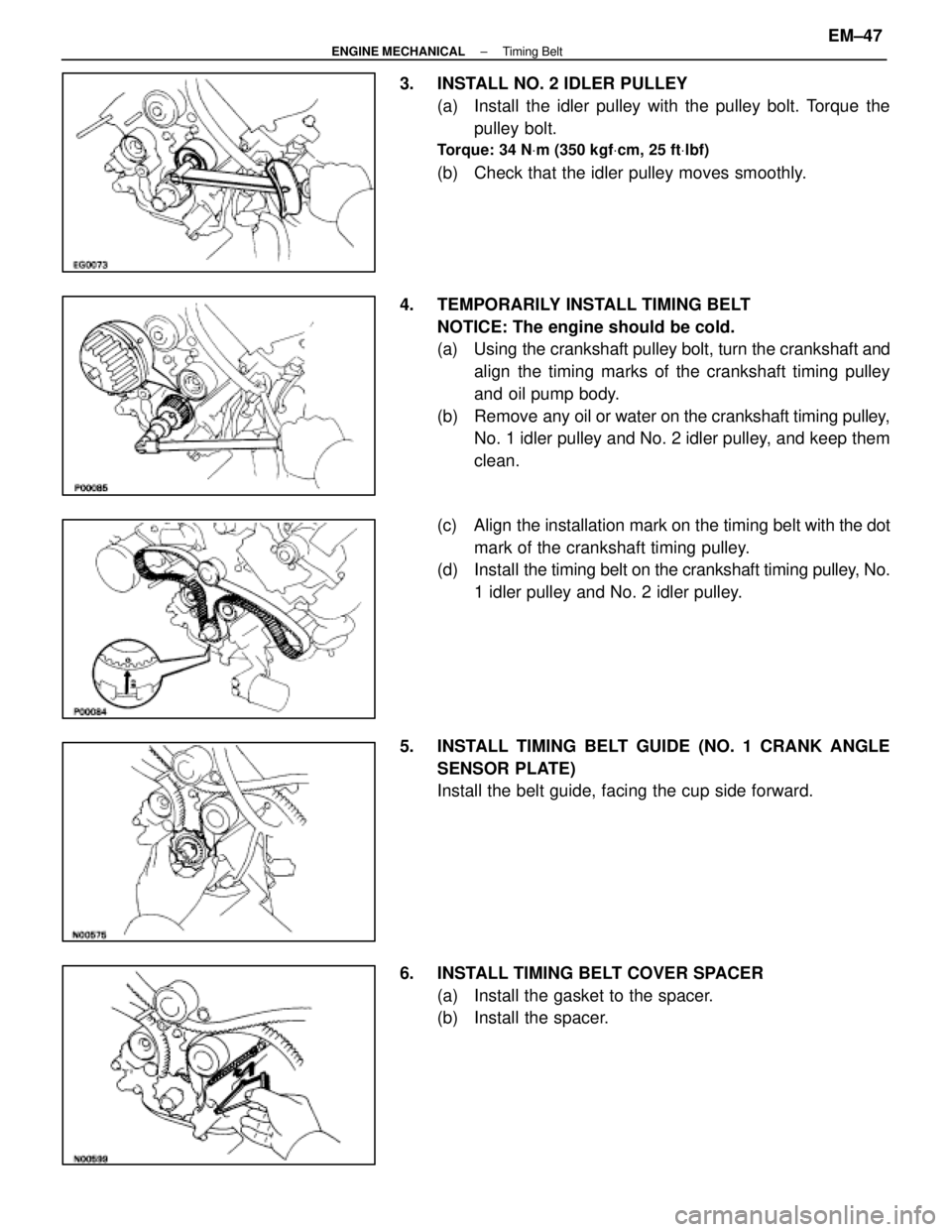
3. INSTALL NO. 2 IDLER PULLEY(a) Install the idler pulley with the pulley bolt. Torque thepulley bolt.
Torque: 34 N Vm (350 kgf Vcm, 25 ft Vlbf)
(b) Check that the idler pulley moves smoothly.
4. TEMPORARILY INSTALL TIMING BELT NOTICE: The engine should be cold.
(a) Using the crankshaft pulley bolt, turn the crankshaft andalign the timing marks of the crankshaft timing pulley
and oil pump body.
(b) Remove any oil or water on the crankshaft timing pulley,
No. 1 idler pulley and No. 2 idler pulley, and keep them
clean.
(c) Align the installation mark on the timing belt with the dot
mark of the crankshaft timing pulley.
(d) Install the timing belt on the crankshaft timing pulley, No.
1 idler pulley and No. 2 idler pulley.
5. INSTALL TIMING BELT GUIDE (NO. 1 CRANK ANGLE SENSOR PLATE)
Install the belt guide, facing the cup side forward.
6. INSTALL TIMING BELT COVER SPACER (a) Install the gasket to the spacer.
(b) Install the spacer.
±
ENGINE MECHANICAL Timing BeltEM±47
WhereEverybodyKnowsYourName
Page 1723 of 4087
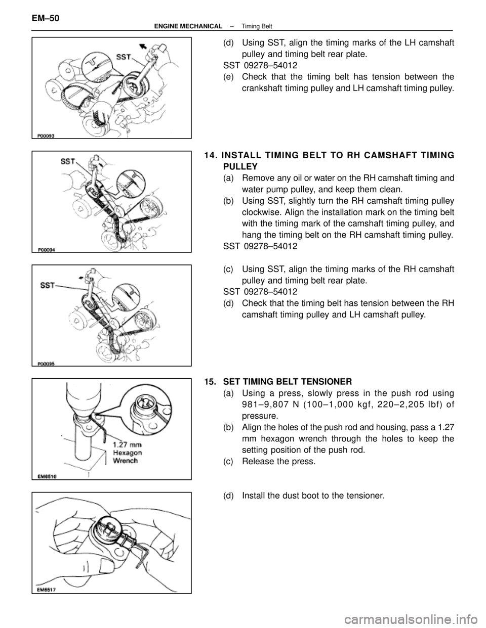
(d) Using SST, align the timing marks of the LH camshaftpulley and timing belt rear plate.
SST 09278±54012
(e) Check that the timing belt has tension between the crankshaft timing pulley and LH camshaft timing pulley.
14. INSTALL TIMING BELT TO RH CAMSHAFT TIMING PULLEY
(a) Remove any oil or water on the RH camshaft timing andwater pump pulley, and keep them clean.
(b) Using SST, slightly turn the RH camshaft timing pulley clockwise. Align the installation mark on the timing belt
with the timing mark of the camshaft timing pulley, and
hang the timing belt on the RH camshaft timing pulley.
SST 09278±54012
(c) Using SST, align the timing marks of the RH camshaft pulley and timing belt rear plate.
SST 09278±54012
(d) Check that the timing belt has tension between the RH
camshaft timing pulley and LH camshaft pulley.
15. SET TIMING BELT TENSIONER (a) Using a press, slowly press in the push rod using981±9,807 N (100±1,000 kgf, 220±2,205 lbf) of
pressure.
(b) Align the holes of the push rod and housing, pass a 1.27
mm hexagon wrench through the holes to keep the
setting position of the push rod.
(c) Release the press.
(d) Install the dust boot to the tensioner.
EM±50
±
ENGINE MECHANICAL Timing Belt
WhereEverybodyKnowsYourName
Page 1741 of 4087
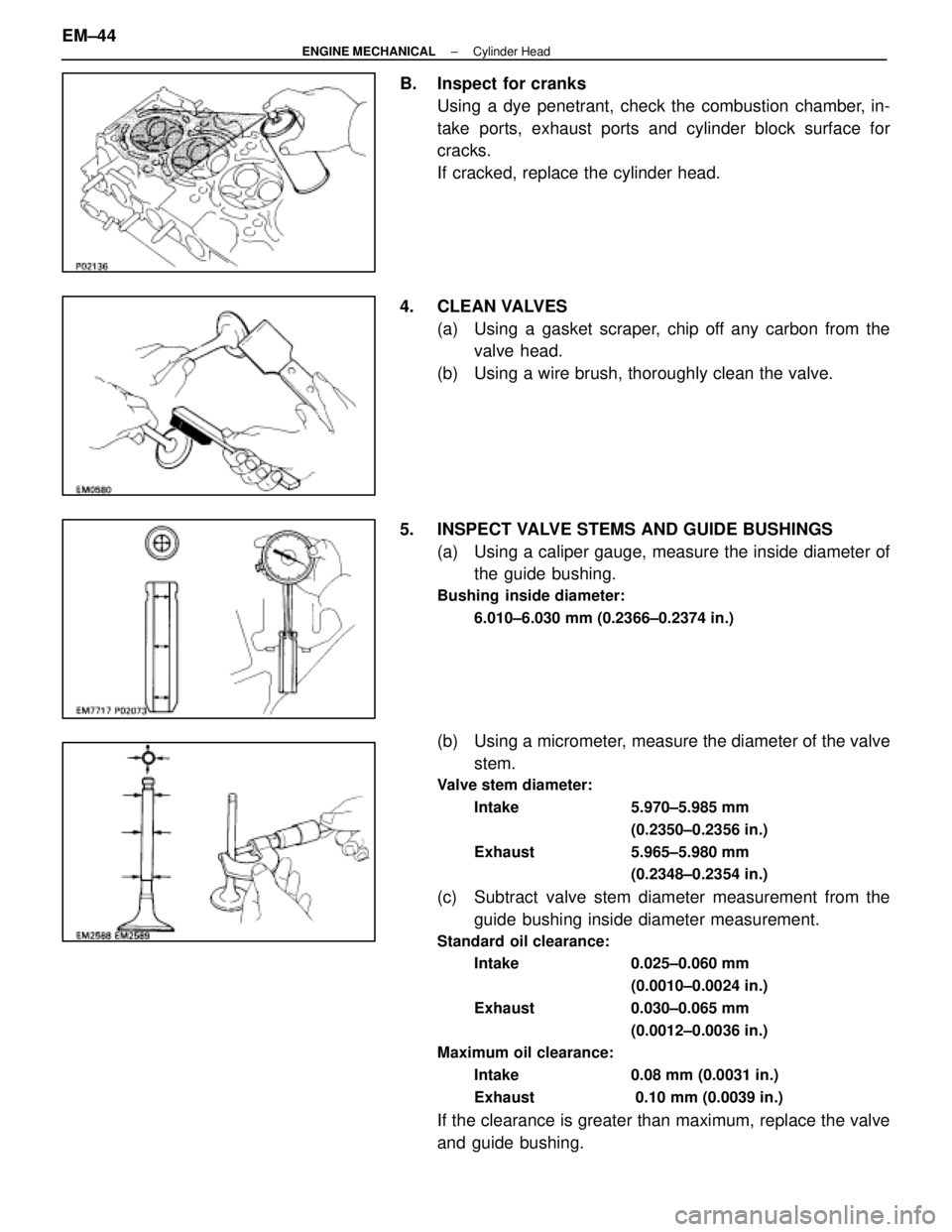
B. Inspect for cranksUsing a dye penetrant, check the combustion chamber, in-
take ports, exhaust ports and cylinder block surface for
cracks.
If cracked, replace the cylinder head.
4. CLEAN VALVES (a) Using a gasket scraper, chip off any carbon from thevalve head.
(b) Using a wire brush, thoroughly clean the valve.
5. INSPECT VALVE STEMS AND GUIDE BUSHINGS (a) Using a caliper gauge, measure the inside diameter ofthe guide bushing.
Bushing inside diameter:
6.010±6.030 mm (0.2366±0.2374 in.)
(b) Using a micrometer, measure the diameter of the valvestem.
Valve stem diameter:
Intake 5.970±5.985 mm (0.2350±0.2356 in.)
Exhaust 5.965±5.980 mm (0.2348±0.2354 in.)
(c) Subtract valve stem diameter measurement from theguide bushing inside diameter measurement.
Standard oil clearance:
Intake 0.025±0.060 mm
(0.0010±0.0024 in.)
Exhaust 0.030±0.065 mm (0.0012±0.0036 in.)
Maximum oil clearance:
Intake 0.08 mm (0.0031 in.)
Exhaust 0.10 mm (0.0039 in.)
If the clearance is greater than maximum, replace the valve
and guide bushing.
EM±44
±
ENGINE MECHANICAL Cylinder Head
WhereEverybodyKnowsYourName
Page 1746 of 4087
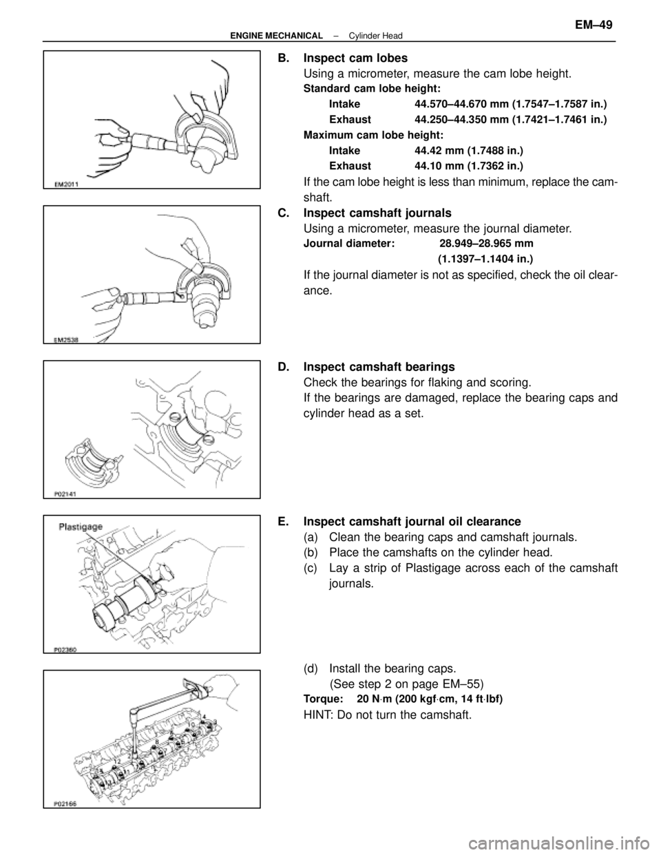
B. Inspect cam lobesUsing a micrometer, measure the cam lobe height.
Standard cam lobe height:
Intake 44.570±44.670 mm (1.7547±1.7587 in.)
Exhaust 44.250±44.350 mm (1.7421±1.7461 in.)
Maximum cam lobe height: Intake 44.42 mm (1.7488 in.)
Exhaust 44.10 mm (1.7362 in.)
If the cam lobe height is less than minimum, replace the cam-
shaft.
C. Inspect camshaft journals Using a micrometer, measure the journal diameter.
Journal diameter: 28.949±28.965 mm
(1.1397±1.1404 in.)
If the journal diameter is not as specified, check the oil clear-
ance.
D. Inspect camshaft bearings Check the bearings for flaking and scoring.
If the bearings are damaged, replace the bearing caps and
cylinder head as a set.
E. Inspect camshaft journal oil clearance (a) Clean the bearing caps and camshaft journals.
(b) Place the camshafts on the cylinder head.
(c) Lay a strip of Plastigage across each of the camshaftjournals.
(d) Install the bearing caps. (See step 2 on page EM±55)
Torque: 20 N Vm (200 kgf Vcm, 14 ft Vlbf)
HINT: Do not turn the camshaft.
±
ENGINE MECHANICAL Cylinder HeadEM±49
WhereEverybodyKnowsYourName
Page 1751 of 4087
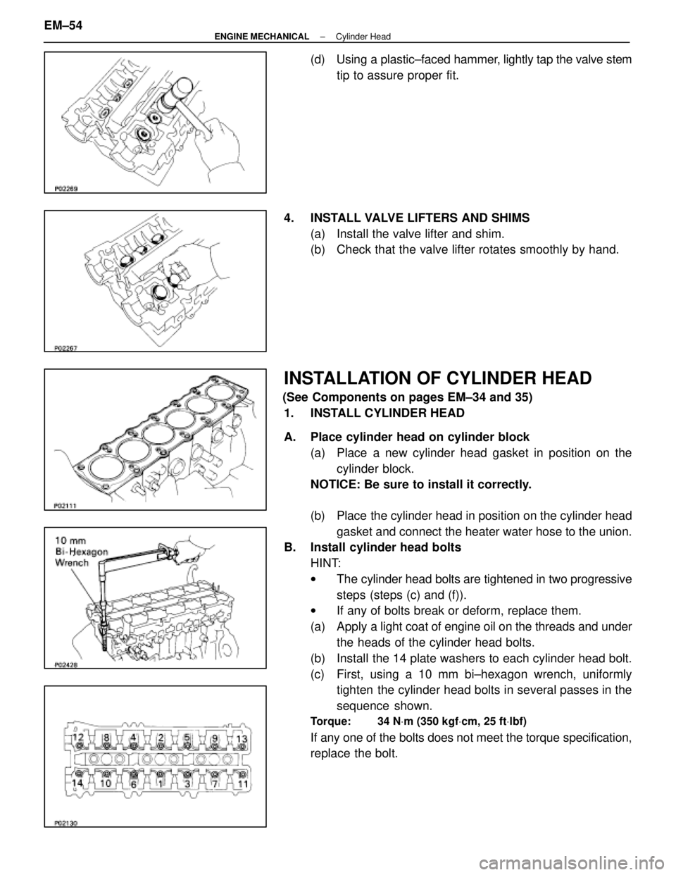
(d) Using a plastic±faced hammer, lightly tap the valve stem
tip to assure proper fit.
4. INSTALL VALVE LIFTERS AND SHIMS (a) Install the valve lifter and shim.
(b) Check that the valve lifter rotates smoothly by hand.
INSTALLATION OF CYLINDER HEAD
(See Components on pages EM±34 and 35)1. INSTALL CYLINDER HEAD
A. Place cylinder head on cylinder block (a) Place a new cylinder head gasket in position on thecylinder block.
NOTICE: Be sure to install it correctly.
(b) Place the cylinder head in position on the cylinder head
gasket and connect the heater water hose to the union.
B. Install cylinder head bolts
HINT:
wThe cylinder head bolts are tightened in two progressive
steps (steps (c) and (f)).
w If any of bolts break or deform, replace them.
(a) Apply a light coat of engine oil on the threads and under
the heads of the cylinder head bolts.
(b) Install the 14 plate washers to each cylinder head bolt.
(c) First, using a 10 mm bi±hexagon wrench, uniformly tighten the cylinder head bolts in several passes in the
sequence shown.
Torque: 34 N Vm (350 kgf Vcm, 25 ft Vlbf)
If any one of the bolts does not meet the torque specification,
replace the bolt.
EM±54
±
ENGINE MECHANICAL Cylinder Head
WhereEverybodyKnowsYourName