Page 1802 of 4087
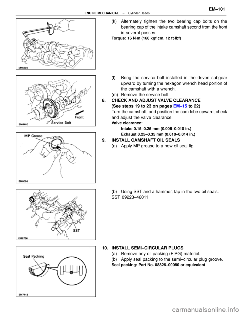
(k) Alternately tighten the two bearing cap bolts on thebearing cap of the intake camshaft second from the front
in several passes.
Torque: 16 N Vm (160 kgf Vcm, 12 ft Vlbf)
(l) Bring the service bolt installed in the driven subgear
upward by turning the hexagon wrench head portion of
the camshaft with a wrench.
(m) Remove the service bolt.
8. CHECK AND ADJUST VALVE CLEARANCE (See steps 19 to 23 on pages EM±15 to 22)
Turn the camshaft, and position the cam lobe upward, check
and adjust the valve clearance.
Valve clearance:
Intake 0.15±0.25 mm (0.006±0.010 in.)
Exhaust 0.25±0.35 mm (0.010±0.014 in.)
9. INSTALL CAMSHAFT OIL SEALS(a) Apply MP grease to a new oil seal lip.
(b) Using SST and a hammer, tap in the two oil seals.
SST 09223±46011
10. INSTALL SEMI±CIRCULAR PLUGS (a) Remove any oil packing (FIPG) material.
(b) Apply seal packing to the semi±circular plug groove.
Seal packing: Part No. 08826±00080 or equivalent
±
ENGINE MECHANICAL Cylinder HeadsEM±101
WhereEverybodyKnowsYourName
Page 1822 of 4087
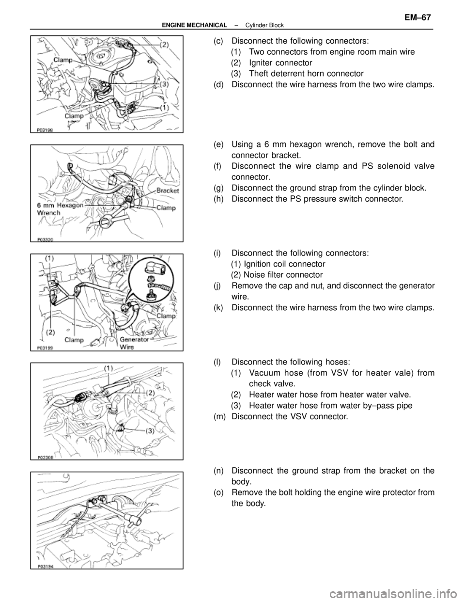
(c) Disconnect the following connectors:(1) Two connectors from engine room main wire
(2) Igniter connector
(3) Theft deterrent horn connector
(d) Disconnect the wire harness from the two wire clamps.
(e) Using a 6 mm hexagon wrench, remove the bolt and connector bracket.
(f) Disc onnect the wire clamp and PS solenoid valve
connector.
(g) Disconnect the ground strap from the cylinder block.
(h) Disconnect the PS pressure switch connector.
(i) Disconnect the following connectors: (1) Ignition coil connector
(2) Noise filter connector
(j) Remove the cap and nut, and disconnect the generator wire.
(k) Disconnect the wire harness from the two wire clamps.
(l) Disconnect the following hoses: (1) Vacuum hose (from VSV for heater vale) from check valve.
(2) Heater water hose from heater water valve.
(3) Heater water hose from water by±pass pipe
(m) Disconnect the VSV connector.
(n) Disconnect the ground strap from the bracket on the body.
(o) Remove the bolt holding the engine wire protector from
the body.
±
ENGINE MECHANICAL Cylinder BlockEM±67
WhereEverybodyKnowsYourName
Page 1832 of 4087
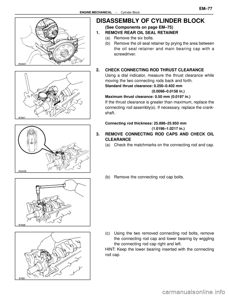
DISASSEMBLY OF CYLINDER BLOCK
(See Components on page EM±75)
1. REMOVE REAR OIL SEAL RETAINER (a) Remove the six bolts.
(b) Remove the oil seal retainer by prying the area between
the oil seal retainer and main bearing cap with a
screwdriver.
2. CHECK CONNECTING ROD THRUST CLEARANCE Using a dial indicator, measure the thrust clearance while
moving the two connecting rods back and forth.
Standard thrust clearance: 0.250±0.402 mm
(0.0098±0.0158 in.)
Maximum thrust clearance: 0.50 mm (0.0197 in.)
If the thrust clearance is greater than maximum, replace the
connecting rod assembly(s). If necessary, replace the crank-
shaft.
Connecting rod thickness: 25.898±25.950 mm (1.0196±1.0217 in.)
3. REMOVE CONNECTING ROD CAPS AND CHECK OILCLEARANCE
(a) Check the matchmarks on the connecting rod and cap.
(b) Remove the connecting rod cap bolts.
(c) Using the two removed connecting rod bolts, removethe connecting rod cap and lower bearing by wiggling
the connecting rod cap right and left.
HINT: Keep the lower bearing inserted with the connecting
rod cap.
±
ENGINE MECHANICAL Cylinder BlockEM±77
WhereEverybodyKnowsYourName
Page 1835 of 4087
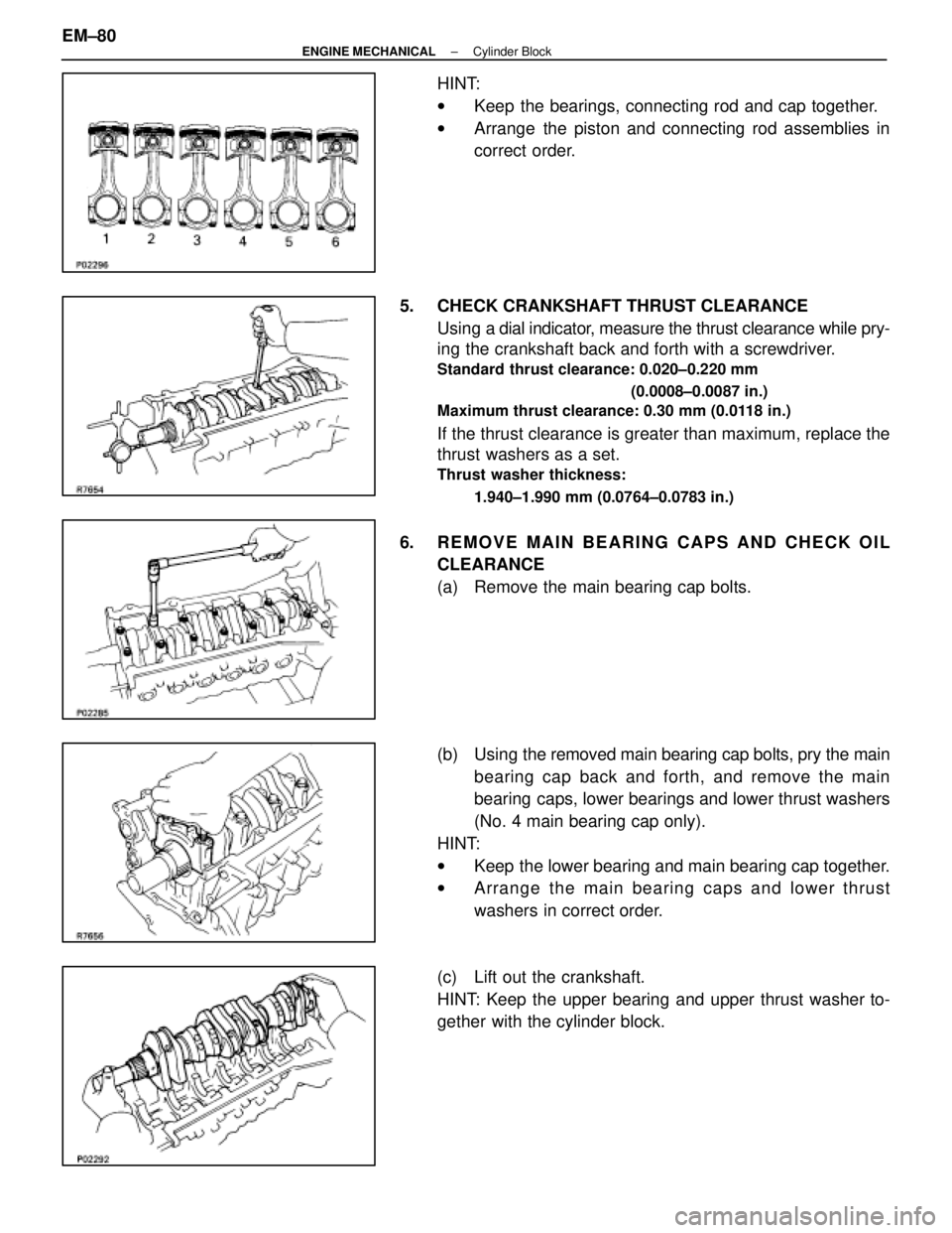
HINT:
wKeep the bearings, connecting rod and cap together.
w Arrange the piston and connecting rod assemblies in
correct order.
5. CHECK CRANKSHAFT THRUST CLEARANCE Using a dial indi cator, measure the thrust clearance while pry-
ing the crankshaft back and forth with a screwdriver.
Standard thrust clearance: 0.020±0.220 mm
(0.0008±0.0087 in.)
Maximum thrust clearance: 0.30 mm (0.0118 in.)
If the thrust clearance is greater than maximum, replace the
thrust washers as a set.
Thrust washer thickness:
1.940±1.990 mm (0.0764±0.0783 in.)
6. REMOVE MAIN BEARING CAPS AND CHECK OILCLEARANCE
(a) Remove the main bearing cap bolts.
(b) Using the removed main bearing cap bolts, pry the main
bearing cap back and forth, and remove the main
bearing caps, lower bearings and lower thrust washers
(No. 4 main bearing cap only).
HINT:
w Keep the lower bearing and main bearing cap together.
w Arrange the main bearing caps and lower thrust
washers in correct order.
(c) Lift out the crankshaft.
HINT: Keep the upper bearing and upper thrust washer to-
gether with the cylinder block.
EM±80
±
ENGINE MECHANICAL Cylinder Block
WhereEverybodyKnowsYourName
Page 1836 of 4087
(d) Clean each main journal and bearing.
(e) Check each main journal and bearing for pitting andscratches.
If the journal or bearing is damaged, replace the bearings.
If necessary, grind or replace the crankshaft.
(f) Place the crankshaft on the cylinder block.
(g) Lay a strip of Plastigage across each journal.
(h) Install the main bearing caps.
(See step 4 on pages EM±97 and 98)
Torque: 1st 44 N Vm (450 kgf Vcm, 33 ft Vlbf)
2nd turn 90 5
HINT: Do not turn the crankshaft.
(i) Remove the main bearing caps.
(See procedures (a) and (b) above)
(j) Measure the Plastigage at its widest point.
Standard clearance:
STD size 0.026±0.040 mm (0.0010±0.0016 in.)
U/S 0.25 0.025±0.061 mm (0.0010±0.0024 in.)
Maximum clearance: STD size 0.06 mm (0.0024 in.)
U/S 0.25 0.08 mm (0.0031 in.)
If the oil clearance is greater than maximum, replace the bearings.
If necessary, replace the crankshaft.
±
ENGINE MECHANICAL Cylinder BlockEM±81
WhereEverybodyKnowsYourName
Page 1840 of 4087
5. REMOVE CYLINDER RIDGEIf the wear is less than 0.2 mm (0.008 in.), using a ridge ream-
er, grind the top of the cylinder.
6. INSPECT MAIN BEARING CAP BOLTS Using vernier calipers, measure the minimum diameter of the
compressed thread at the measuring point.
Standard diameter: 9.96±9.97 mm
(0.3921±0.3925 in.)
Minimum diameter: 9.7 mm (0.3819 in.)
If the diameter is less than minimum, replace the bolt.
DISASSEMBLY OF PISTON AND
CONNECTING ROD ASSEMBLIES
1. CHECK FIT BETWEEN PISTON AND PISTON PIN Try to move the piston back and forth on the piston pin.
If any movement is felt, replace the piston and pin as a set.
2. REMOVE PISTON RINGS
(a) Using a piston ring expander, remove the two compression rings.
(b) Remove the two side rails and oil ring expander by hand. HINT: Arrange the piston rings in correct order only.
±
ENGINE MECHANICAL Cylinder BlockEM±85
WhereEverybodyKnowsYourName
Page 1844 of 4087
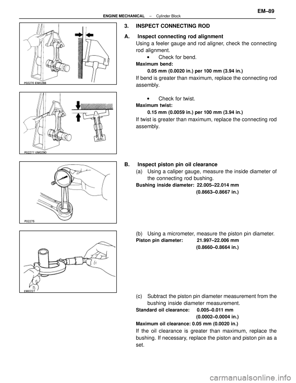
3. INSPECT CONNECTING ROD
A. Inspect connecting rod alignmentUsing a feeler gauge and rod aligner, check the connecting
rod alignment.w Check for bend.
Maximum bend:
0.05 mm (0.0020 in.) per 100 mm (3.94 in.)
If bend is greater than maximum, replace the connecting rod
assembly.
w Check for twist.
Maximum twist:
0.15 mm (0.0059 in.) per 100 mm (3.94 in.)
If twist is greater than maximum, replace the connecting rod
assembly.
B. Inspect piston pin oil clearance (a) Using a caliper gauge, measure the inside diameter ofthe connecting rod bushing.
Bushing inside diameter: 22.005±22.014 mm
(0.8663±0.8667 in.)
(b) Using a micrometer, measure the piston pin diameter.
Piston pin diameter: 21.997±22.006 mm(0.8660±0.8664 in.)
(c) Subtract the piston pin diameter measurement from thebushing inside diameter measurement.
Standard oil clearance: 0.005±0.011 mm
(0.0002±0.0004 in.)
Maximum oil clearance: 0.05 mm (0.0020 in.)
If the oil clearance is greater than maximum, replace the
bushing. If necessary, replace the piston and piston pin as a
set.
±
ENGINE MECHANICAL Cylinder BlockEM±89
WhereEverybodyKnowsYourName
Page 1845 of 4087
C. If necessary, replace connecting rod bushing(a) Using SST and a press, press out the bushing.
SST 09222±30010
(b) Align the oil holes of a new bushing and the connectingrod.
(c) Using SST and a press, press in the bushing.
SST 09222±30010
(d) Using a pin hole grinder, bore the bushing to obtain the
standard specified clearance (see step B above)
between the bushing and piston pin.
(e) Check the piston pin fit at room temperature.
Coat the piston pin with engine oil, and push it into the con-
necting rod with your thumb.
D. Inspect connecting rod bolts Using vernier calipers, measure the minimum diameter of the
compressed bolt at the measuring point.
Standard diameter: 8.2±8.3 mm
(0.325±0.327 in.)
Minimum diameter: 8.0 mm (0.315 in.)
If the diameter is less than minimum, replace the connecting
rod bolt.
EM±90
±
ENGINE MECHANICAL Cylinder Block
WhereEverybodyKnowsYourName