Page 1846 of 4087
INSPECTION OF CRANKSHAFT
1. INSPECT CRANKSHAFT FOR RUNOUT(a) Place the crankshaft on V±blocks.
(b) Using a dial indicator, measure the circle runout at thecenter journal.
Maximum circle runout: 0.06 mm (0.0024 in.)
If the circle runout is greater than maximum, replace the
crankshaft.
2. INSPECT MAIN JOURNALS AND CRANK PINS (a) Using a micr ometer, measure the diameter of each main
journal and crank pin.
Main journal diameter: 61.984±62.000 mm
(2.4403±2.4409 in.)
Crank pin diameter: 51.982±52.000 mm (2.0465±2.0472 in.)
If the diameter is not as specified, check the oil clearance
(See page EM±77 or EM±80).
(b) Check each main journal and crank pin for taper andout±of±round as shown.
Maximum taper and out±of round: 0.02 mm
(0.0008 in.)
If the taper or out±of±round is greater than maximum, re-
place the crankshaft.
±
ENGINE MECHANICAL Cylinder BlockEM±91
WhereEverybodyKnowsYourName
Page 1854 of 4087

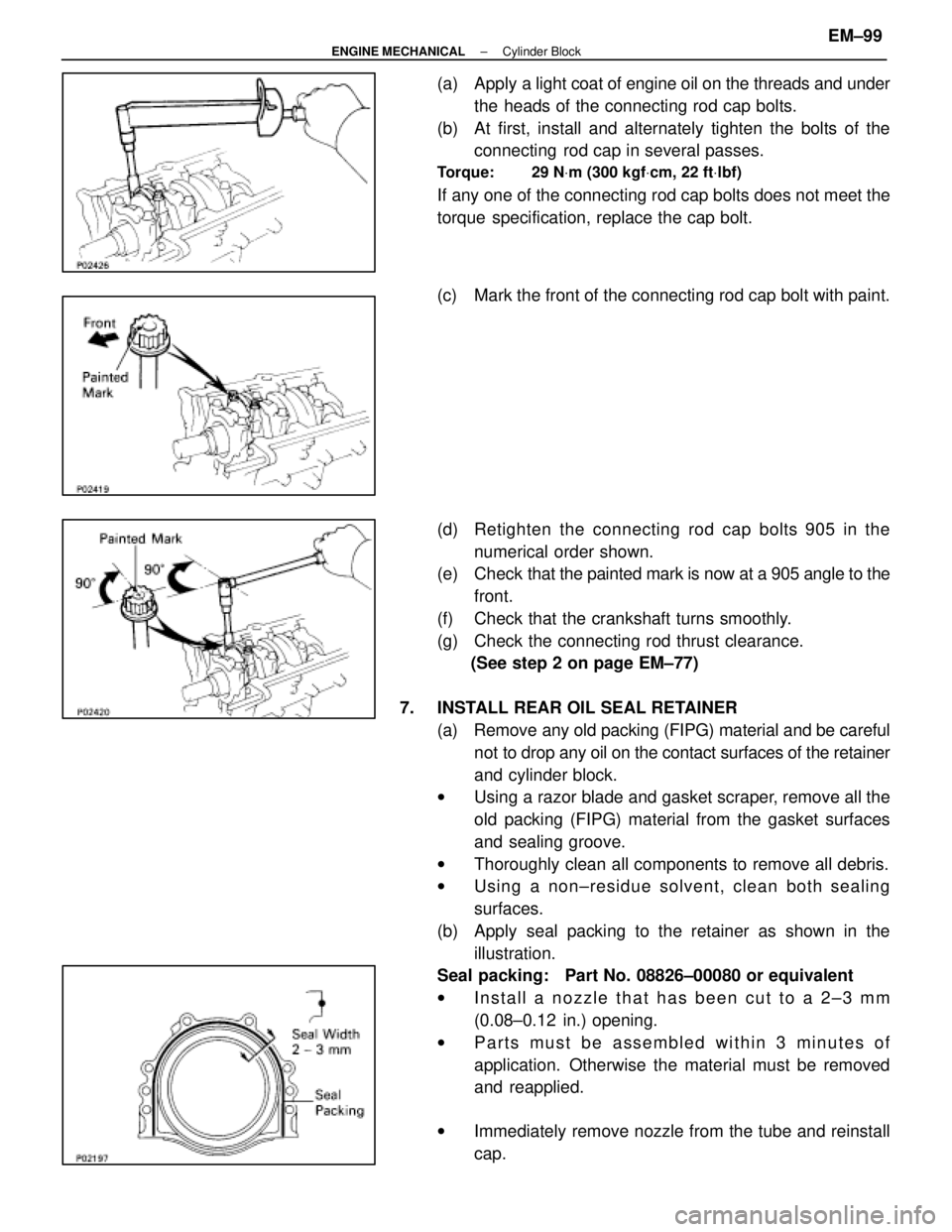
(a) Apply a light coat of engine oil on the threads and under
the heads of the connecting rod cap bolts.
(b) At first, install and alternately tighten the bolts of the connecting rod cap in several passes.
Torque: 29 N Vm (300 kgf Vcm, 22 ft Vlbf)
If any one of the connecting rod cap bolts does not meet the
torque specification, replace the cap bolt.
(c) Mark the front of the connecting rod cap bolt with paint.
(d) Retighten the connecting rod cap bolts 905 in the
numerical order shown.
(e) Check that the painted mark is now at a 905 angle to the
front.
(f) Check that the crankshaft turns smoothly.
(g) Check the connecting rod thrust clearance. (See step 2 on page EM±77)
7. INSTALL REAR OIL SEAL RETAINER (a) Remove any old packing (FIPG) material and be carefulnot to drop any oil on the contact surfaces of the retainer
and cylinder block.
w Using a razor blade and gasket scraper, remove all the
old packing (FIPG) material from the gasket surfaces
and sealing groove.
w Thoroughly clean all components to remove all debris.
w Using a non±residue solvent, clean both sealing
surfaces.
(b) Apply seal packing to the retainer as shown in the illustration.
Seal packing: Part No. 08826±00080 or equivalent
w Install a nozzle that has been cut to a 2±3 mm
(0.08±0.12 in.) opening.
w Parts must be assembled within 3 minutes of
application. Otherwise the material must be removed
and reapplied.
w Immediately remove nozzle from the tube and reinstall
cap.
±
ENGINE MECHANICAL Cylinder BlockEM±99
WhereEverybodyKnowsYourName
Page 1864 of 4087

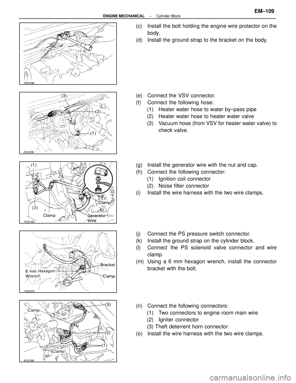
(c) Install the bolt holding the engine wire protector on thebody.
(d) Install the ground strap to the bracket on the body.
(e) Connect the VSV connector.
(f) Connect the following hose: (1) Heater water hose to water by±pass pipe
(2) Heater water hose to heater water valve
(3) Vacuum hose (from VSV for heater water valve) to
check valve.
(g) Install the generator wire with the nut and cap.
(h) Connect the following connector: (1) Ignition coil connector
(2) Noise filter connector
(i) Install the wire harness with the two wire clamps.
(j) Connect the PS pressure switch connector.
(k) Install the ground strap on the cylinder block.
(l) Connect the PS solenoid valve connector and wire
clamp.
(m) Using a 6 mm hexagon wrench, install the connector bracket with the bolt.
(n) Connect the following connectors: (1) Two connectors to engine room main wire
(2) Igniter connector
(3) Theft deterrent horn connector
(o) Install the wire harness with the two wire clamps.
±
ENGINE MECHANICAL Cylinder BlockEM±109
WhereEverybodyKnowsYourName
Page 1867 of 4087

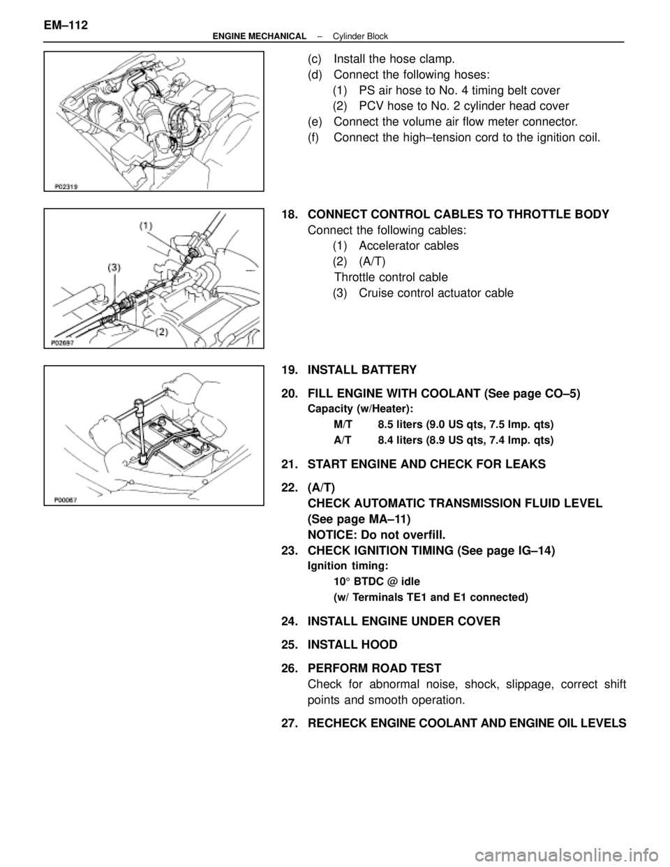
(c) Install the hose clamp.
(d) Connect the following hoses:(1) PS air hose to No. 4 timing belt cover
(2) PCV hose to No. 2 cylinder head cover
(e) Connect the volume air flow meter connector.
(f) Connect the high±tension cord to the ignition coil.
18. CONNECT CONTROL CABLES TO THROTTLE BODY Connect the following cables:(1) Accelerator cables
(2) (A/T)
Throttle control cable
(3) Cruise control actuator cable
19. INSTALL BATTERY
20. FILL ENGINE WITH COOLANT (See page CO±5)
Capacity (w/Heater): M/T 8.5 liters (9.0 US qts, 7.5 lmp. qts)
A/T 8.4 liters (8.9 US qts, 7.4 lmp. qts)
21. START ENGINE AND CHECK FOR LEAKS
22. (A/T)CHECK AUTOMATIC TRANSMISSION FLUID LEVEL
(See page MA±11)
NOTICE: Do not overfill.
23. CHECK IGNITION TIMING (See page IG±14)
Ignition timing:
105 BTDC @ idle
(w/ Terminals TE1 and E1 connected)
24. INSTALL ENGINE UNDER COVER
25. INSTALL HOOD
26. PERFORM ROAD TEST Check for abnormal noise, shock, slippage, correct shift
points and smooth operation.
27. RECHECK ENGINE COOLANT AND ENGINE OIL LEVELS
EM±112
±
ENGINE MECHANICAL Cylinder Block
WhereEverybodyKnowsYourName
Page 1977 of 4087
Preparation
SST (SPECIAL SERVICE TOOLS)
IllustrationPart No.Part NameNote
09268±41045Injection Measuring
Tool Set
(90268±41070)No. 4 Union
Injector
(09268±41080)No. 6 Union
Cold start Injector
(09268±52010)Injection Measuring
Attachment
Injector
09268±45012EFI Fuel Pressure
Gauge
09612±24014
Steering Gear
Housing Overhaul
Tool Set
(09617±24011)Steering Rack Wrench
Fuel pressure pulsation damper
09631±22020
Power Steering
Hose Nut 14 X 17 mm
Wrench SetFuel line flare nut
09816±30010Oil Pressure
Switch SocketKnock sensor
09842±30055Wire ªGº
EFI Inspection
Cold start Injector
09842±30070Wire ªFº
EFI Inspection
Injector
09843±18020Diagnosis Check
Wire
0990±01000
Engine Control
Computer
Check Harness ªAº
FI±10 ± PreparationEFI SYSTEM
WhereEverybodyKnowsYourName
Page 1993 of 4087
Fuel Cut RPM
INSPECTION OF FUEL CUT RPM
1. WARM UP ENGINEAllow the engine to warm up to normal operating
temperature.
2. CONNECT TACHOMETER Connect the test probe of a tachometer to terminal IG of the
check connector.
NOTICE
w Never allow the tachometer terminal to touch ground as
it could result in damage to the igniter and/or ignition
coil.
w As some tachometers are not compatible with this
ignition system, we recommend that you confirm the
compatibility of yours before use.
3. INSPECT FUEL CUT OPERATION
(a) Increase the engine speed to at least 2,500 rpm.
(b) Check for injector operating noise.
(c) Check that when the throttle lever is released, injectoroperation noise stops momentarily and then resumes.
HINT:
w The vehicle should be stopped.
w Measure with the A/C OFF.
Fuel return rpm: 1,400 rpm
4. REMOVE TACHOMETER
FI±136
± Electronic Control System (Fuel \
Cut RPM)EFI SYSTEM
WhereEverybodyKnowsYourName
Page 2014 of 4087
PREPARATION
SST (SPECIAL SERVICE TOOLS)
IllustrationPart No.Part NameNote
09268±41045Injection Measuring
Tool Set
(09268±41090)(No. 7 Union)
Injector
(09268±52010)(Injection Measuring
Attachment)
Injector
(09405±09015)(No. 1 Union)
Injector
09268±45012EFI Fuel Pressure
Gauge
09612±24014
Steering Gear
Housing Overhaul
Tool Set
(09617±24011(Steering Rack Wrench)
Fuel pressure pulsation damper
09631±22020
Power Steering
Hose Nut 14 x 17 mm
Wrench SetFuel line flare nut
09816±30010Oil Pressure
Switch Socket
Knock sensor
09842±30070Wire ªFº
EFI Inspection
Injector
09843±18020Diagnosis Check
Wire
09990±01000
Engine Control
Computer Check
Harness ªAº
±
EFI SYSTEM PreparationFI±9
WhereEverybodyKnowsYourName
Page 2016 of 4087
Preparation
SST (SPECIAL SERVICE TOOLS)
IllustrationPart No.Part NameNote
09268±41045Injection Measuring
Tool Set
(90268±41070)No. 4 Union
Injector
(09268±41080)No. 6 Union
Cold start Injector
(09268±52010)Injection Measuring
Attachment
Injector
09268±45012EFI Fuel Pressure
Gauge
09612±24014
Steering Gear
Housing Overhaul
Tool Set
(09617±24011)Steering Rack Wrench
Fuel pressure pulsation damper
09631±22020
Power Steering
Hose Nut 14 X 17 mm
Wrench SetFuel line flare nut
09816±30010Oil Pressure
Switch SocketKnock sensor
09842±30055Wire ªGº
EFI Inspection
Cold start Injector
09842±30070Wire ªFº
EFI Inspection
Injector
09843±18020Diagnosis Check
Wire
0990±01000
Engine Control
Computer
Check Harness ªAº
FI±10 ± PreparationEFI SYSTEM
WhereEverybodyKnowsYourName