Page 2095 of 4087
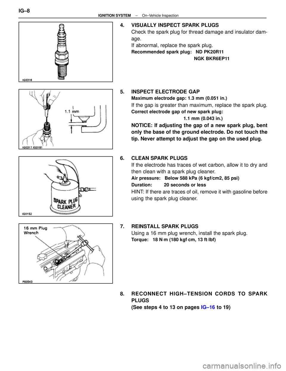
4. VISUALLY INSPECT SPARK PLUGSCheck the spark plug for thread damage and insulator dam-
age.
If abnormal, replace the spark plug.
Recommended spark plug: ND PK20R11
NGK BKR6EP11
5. INSPECT ELECTRODE GAP
Maximum electrode gap: 1.3 mm (0.051 in.)
If the gap is greater than maximum, replace the spark plug.
Correct electrode gap of new spark plug:1.1 mm (0.043 in.)
NOTICE: If adjusting the gap of a new spark plug, bent
only the base of the ground electrode. Do not touch the
tip. Never attempt to adjust the gap on the used plug.
6. CLEAN SPARK PLUGS If the electrode has traces of wet carbon, allow it to dry and
then clean with a spark plug cleaner.
Air pressure: Below 588 kPa (6 kgf/cm2, 85 psi)
Duration: 20 seconds or less
HINT: If there are traces of oil, remove it with gasoline before
using the spark plug cleaner.
7. REINSTALL SPARK PLUGS Using a 16 mm plug wrench, install the spark plug.
Torque: 18 N Vm (180 kgf Vcm, 13 ft Vlbf)
8. RECONNECT HIGH±TENSION CORDS TO SPARK
PLUGS
(See steps 4 to 13 on pages IG±16 to 19)
IG±8
±
IGNITION SYSTEM On±Vehicle Inspection
WhereEverybodyKnowsYourName
Page 2104 of 4087
wAlign the spline of the ignition coil with the spline of
the holder, and slide on the holder.
NOTICE: Check that holder is correctly installed to the
grommet and ignition coil as shown in the illustration. w Check that the lock claw of the holder is engaged
by lightly pulling the holder.
5. INSTALL RH NO.3 TIMING BELT COVER (a) Install the three gaskets to the timing belt cover.
(b) Fit portion A of the timing belt cover, matching it with the
lower high±tension cord cover.
(c) Install the timing belt cover with the three bolts.
±
IGNITION SYSTEM High±Tension Cords and Cord ClampsIG±17
WhereEverybodyKnowsYourName
Page 2107 of 4087
SERVICE SPECIFICATIONS
SERVICE DATA
IgnitionT/M in N range105 BTDC @ idle
timing[Check connector terminals TE1 and E1 con-
nect]
Spark plugTypeNDPK16R11
NGK BKR5EP11
GAPSTD 1.1 mm0.043 in.
Limit 1.3 mm0.051 in.
High±tensionResistanceLimit25 k W per cord
cord
Ignition coilPrimary coil resistance0.2±0.3 �
Secondary coil resistance6±11 k �
DistributorAir gaps0.2±0.4 mm0.008±0.016 in.
Pickup coil resistance (cold)G1±G (±) 125±190 W
G2±G (±) 125±190 W
NE±G (±)155±240 W
±
IGNITION SYSTEM Service SpecificationsIG±15
WhereEverybodyKnowsYourName
Page 2116 of 4087
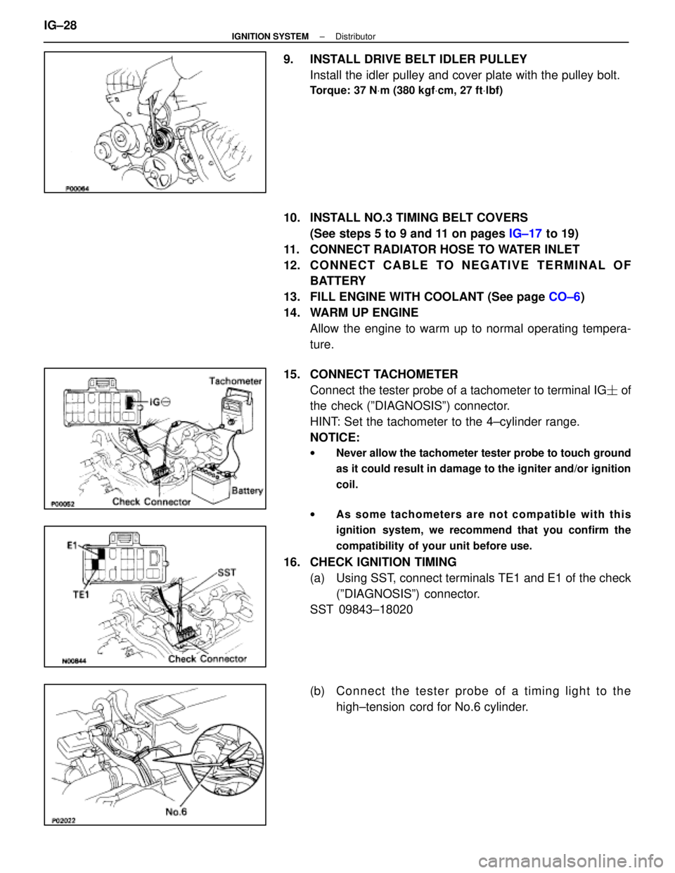
9. INSTALL DRIVE BELT IDLER PULLEYInstall the idler pulley and cover plate with the pulley bolt.
Torque: 37 N Vm (380 kgf Vcm, 27 ft Vlbf)
10. INSTALL NO.3 TIMING BELT COVERS
(See steps 5 to 9 and 11 on pages IG±17 to 19)
11. CONNECT RADIATOR HOSE TO WATER INLET
12. C O N N E C T C A B L E TO N E G AT I V E T E R M I N A L O F BATTERY
13. FILL ENGINE WITH COOLANT (See page CO±6)
14. WARM UP ENGINE Allow the engine to warm up to normal operating tempera-
ture.
15. CONNECT TACHOMETER Connect the tester probe of a tachometer to terminal IG � of
the check (ºDIAGNOSISº) connector.
HINT: Set the tachometer to the 4±cylinder range.
NOTICE:
w Never allow the tachometer tester probe to touch ground
as it could result in damage to the igniter and/or ignition
coil.
w As some tachometers are not compatible with this
ignition system, we recommend that you confirm the
compatibility of your unit before use.
16. CHECK IGNITION TIMING
(a) Using SST, connect terminals TE1 and E1 of the check(ºDIAGNOSISº) connector.
SST 09843±18020
(b) C onnect the tester probe of a timing light to the
high±tension cord for No.6 cylinder.
IG±28
±
IGNITION SYSTEM Distributor
WhereEverybodyKnowsYourName
Page 2123 of 4087

A pressure feeding lubrication system has been adopted to supply oil to \
the moving parts of this engine. The
lubrication system consists of an oil pan, oil pump, oil filter and other external p\
arts which supply oil to the moving
parts in the engine block. The oil circuit is shown in the illustration at th\
e top of the previous page. Oil from the
oil pan is pumped up by the oil pump. After it passes through the oil fi\
lter, it is fed through the various oil holes
in the crankshaft and cylinder block. After passing through the cylinder b\
lock and performing its lubricating func-
tion, the oil is returned by gravity to the oil pan. A dipstick on the center\
left side of the cylinder block is provided
to check the oil level.
OIL PUMP The oil pump pumps up oil from the oil pan and sends it under pressure to t\
he various parts of the engine.
An oil strainer is mounted in front of the inlet to the oil pump. The oil \
pump itself is a trochoid type pump, inside
of which there is a drive rotor and a driven rotor. When the drive rotor rotates, the driven rotor rotates in the same
direction, and since the axis of the driven rotor shaft is different from the center of the driven rotor, the space
between the two rotors is changed as they rotate. Oil is drawn in when the space\
is wide and is discharged when
the space in narrow.
OIL PRESSURE REGULATOR At high engine speeds, the engine oil supplied by the oil pump exceeds the\
capacity of the engine to utilize
it. For that reason, the oil pressure regulator works to prevent an over\
supply of oil. During normal oil supply, a
coil spring and valve keep the bypass closed, but when too much oil is being \
fed, the pressure become extremely
high, overpowering the force of the spring and opening the valves. This allow\
s the excess oil to flow through
the valve and return to the oil pump inlet.
OIL FILTER The oil filter is a full flow type filter with a built±in paper filter e\
lement. Particles of metal from wear, airborne
dirt, carbon and other impurities can get into the oil during use and co\
uld cause accelerated wear or seizing if
allowed to circulate through the engine. The oil filter, integrated into the oil line, removes these impurities as the
oil passes through it. The filter is mounted outside the engine to simplify\
replacement of the filter element. A relief
valve is also included ahead of the filter element to relieve the high oil pr\
essure in case the filter element be-
comes clogged with impurities. The relief valve opens when the oil pressure o\
verpowers the force of the spring.
Oil passing through the relief valve by±passes the oil filter and flo\
ws directly into the main oil hole in the engine.
±
LUBRICATION SYSTEM PrecautionsLU±3
WhereEverybodyKnowsYourName
Page 2125 of 4087
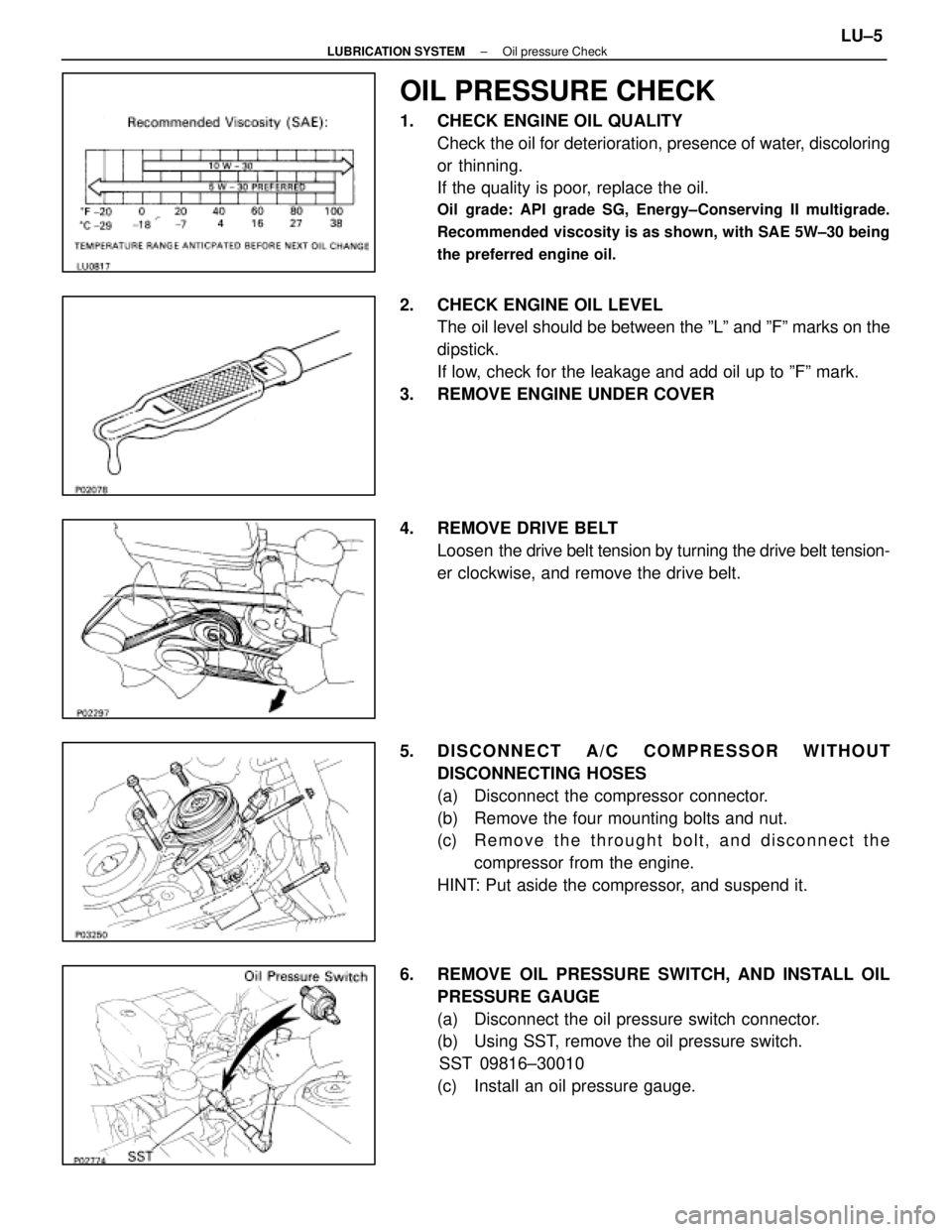
OIL PRESSURE CHECK
1. CHECK ENGINE OIL QUALITYCheck the oil for deterioration, presence of water, discoloring
or thinning.
If the quality is poor, replace the oil.
Oil grade: API grade SG, Energy±Conserving II multigrade.
Recommended viscosity is as shown, with SAE 5W±30 being
the preferred engine oil.
2. CHECK ENGINE OIL LEVELThe oil level should be between the ºLº and ºFº marks on the
dipstick.
If low, check for the leakage and add oil up to ºFº mark.
3. REMOVE ENGINE UNDER COVER
4. REMOVE DRIVE BELT Loosen the drive belt tension by turning the drive belt tension-
er clockwise, and remove the drive belt.
5. DISCONNECT A/C COMPRESSOR WITHOUT DISCONNECTING HOSES
(a) Disconnect the compressor connector.
(b) Remove the four mounting bolts and nut.
(c) R e m o v e t h e t h r ought bolt, and disconnect the
compressor from the engine.
HINT: Put aside the compressor, and suspend it.
6. REMOVE OIL PRESSURE SWITCH, AND INSTALL OIL PRESSURE GAUGE
(a) Disconnect the oil pressure switch connector.
(b) Using SST, remove the oil pressure switch.SST 09816±30010
(c) Install an oil pressure gauge.
±
LUBRICATION SYSTEM Oil pressure CheckLU±5
WhereEverybodyKnowsYourName
Page 2126 of 4087
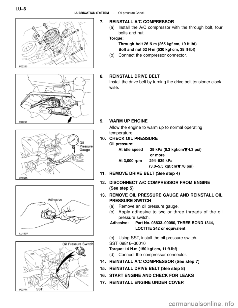
7. REINSTALL A/C COMPRESSOR(a) Install the A/C compressor with the through bolt, fourbolts and nut.
Torque:
Through bolt 26 N Vm (265 kgf Vcm, 19 ft Vlbf)
Bolt and nut 52 N Vm (530 kgf Vcm, 38 ft Vlbf)
(b) Connect the compressor connector.
8. REINSTALL DRIVE BELT Install the drive belt by turning the drive belt tensioner clock-
wise.
9. WARM UP ENGINE Allow the engine to warm up to normal operating
temperature.
10. CHECK OIL PRESSURE
Oil pressure:
At idle speed 29 kPa (0.3 kgf/cm �, 4.3 psi)
or more
At 3,000 rpm 294±539 kPa (3.0±5.5 kgf/cm�, 78 psi)
11. REMOVE DRIVE BELT (See step 4)
12. DISCONNECT A/C COMPRESSOR FROM ENGINE
(See step 5)
13. REMOVE OIL PRESSURE GAUGE AND REINSTALL OIL PRESSURE SWITCH
(a) Remove an oil pressure gauge.
(b) A p p ly a dhesive to two or three threads of the oil
pressure switch.
Adhesive: Part No. 08833±00080, THREE BOND 1344,
LOCTITE 242 or equivalent
(c) Using SST, install the oil pressure switch.
SST 09816±30010
Torque: 14 NVm (150 kgf Vcm, 11 ft Vlbf)
(d) Connect the compressor connector.
14. REINSTALL A/C COMPRESSOR (See step 7)
15. REINSTALL DRIVE BELT (See step 8)
16. START ENGINE AND CHECK FOR LEAKS
17. REINSTALL ENGINE UNDER COVER
LU±6
±
LUBRICATION SYSTEM Oil pressure Check
WhereEverybodyKnowsYourName
Page 2127 of 4087
REPLACEMENT OF ENGINE OIL
AND OIL FILTER
CAUTION:
wProlonged and repeated contact with mineral oil will
result in the removal of natural fats from the skin, leading
to dryness, irritation and dermatitis. In addition, used
engine oil contains potentially harmful contaminants
which may cause skin cancer.
w Exerise caution in order to minimize the length and
frequency of contact of your skin to used oil. Wear
protective clothing and gloves. The skin s hould be
thoroughly w ashed with soap and water, or use waterless
hand cleaner, to remove any used engine oil. Do not use
gasoline, thinners, or solvents.
w In order to preserve the environment, used oil and used
oil filter must be disposed of only at designated disposal
sites.
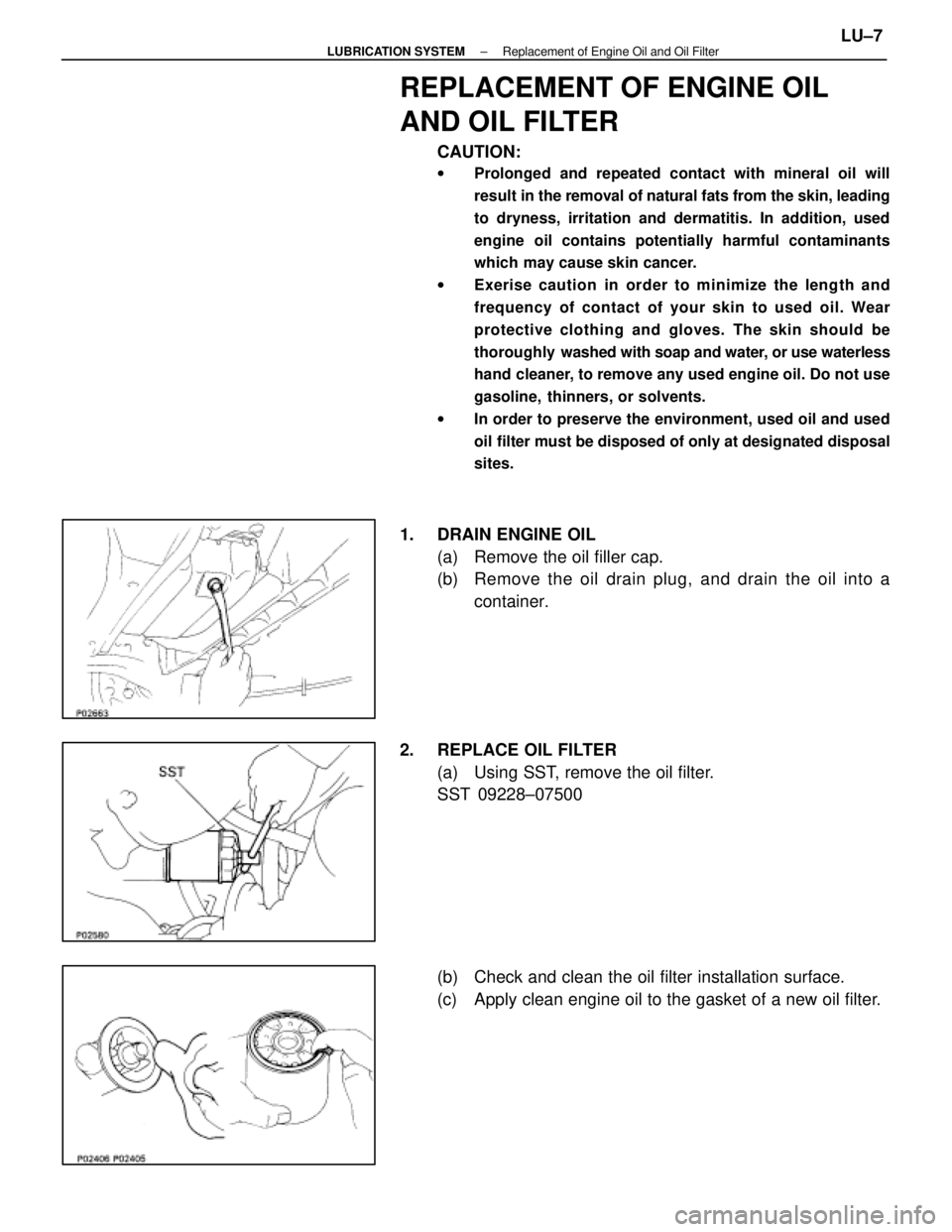
1. DRAIN ENGINE OIL
(a) Remove the oil filler cap.
(b) Remove the oil drain plug, and drain the oil into acontainer.
2. REPLACE OIL FILTER (a) Using SST, remove the oil filter.
SST 09228±07500
(b) Check and clean the oil filter installation surface.
(c) Apply clean engine oil to the gasket of a new oil filter.
±
LUBRICATION SYSTEM Replacement of Engine Oil and Oil FilterLU±7
WhereEverybodyKnowsYourName