Page 15 of 4087

PRECAUTIONS FOR VEHICLES
EQUIPPED WITH A CATALYTIC
CONVERTER
CAUTION: If large amounts of unburned gasoline flow into the
converter, it may overheat and create a fire hazard. To prevent
this, observe the following precautions and explain them to
your customer.
1. Use only unleaded gasoline.
2. Avoid prolonged idling. Avoid running the engine at idle speed for more than 20 min-
utes.
3. Avoid spark jump test. (a) P e r f o r m s p a r k j u m p t e s t o n l y w h e n a b s o l u t e l ynecessary. Perform this test as rapidly as possible.
(b) While testing, never race the engine.
4. Avoid prolonged engine compression measurement.
Engine compression tests must be done as rapidly as pos-
sible.
5. Do not run engine when fuel tank is nearly empty. This may c ause the engine to misfire and create an extra load
on the converter.
6. Avoid coasting with ignition turned off and prolonged braking.
7. Do not dispose of used catalyst along with parts contaminated with gasoline or oil.
IN±12
±
INTRODUCTION Precautions for Vehicles Equipped with a Catalytic
Converter
WhereEverybodyKnowsYourName
Page 46 of 4087

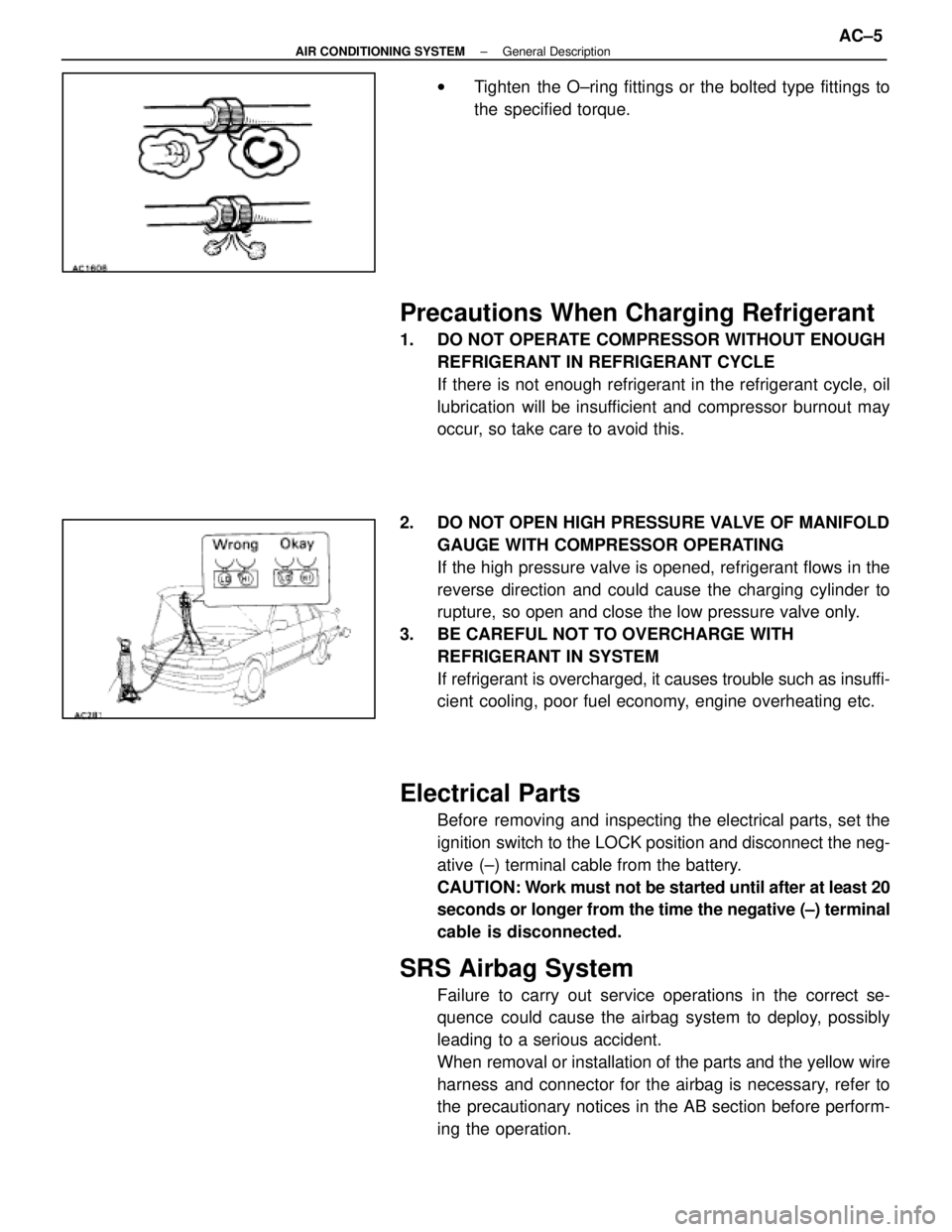
wTighten the O±ring fittings or the bolted type fittings to
the specified torque.
Precautions When Charging Refrigerant
1. DO NOT OPERATE COMPRESSOR WITHOUT ENOUGH
REFRIGERANT IN REFRIGERANT CYCLE
If there is not enough refrigerant in the refrigerant cycle, oil
lubrication will be insufficient and compressor burnout may
occur, so take care to avoid this.
2. DO NOT OPEN HIGH PRESSURE VALVE OF MANIFOLD GAUGE WITH COMPRESSOR OPERATING
If the high pressure valve is opened, refrigerant flows in the
reverse direction and could cause the charging cylinder to
rupture, so open and close the low pressure valve only.
3. BE CAREFUL NOT TO OVERCHARGE WITH REFRIGERANT IN SYSTEM
If refrigerant is overcharged, it causes trouble such as insuffi-
cient cooling, poor fuel economy, engine overheating etc.
Electrical Parts
Before removing and inspecting the electrical parts, set the
ignition switch to the LOCK position and disconnect the neg-
ative (±) terminal cable from the battery.
CAUTION: Work must not be started until after at least 20
seconds or longer from the time the negative (±) terminal
cable is disconnected.
SRS Airbag System
Failure to carry out service operations in the correct se-
quence could cause the airbag system to deploy, possibly
leading to a serious accident.
When removal or installation of the parts and the yellow wire
harness and connector for the airbag is necessary, refer to
the precautionary notices in the AB section before perform-
ing the operation.
±
AIR CONDITIONING SYSTEM General DescriptionAC±5
WhereEverybodyKnowsYourName
Page 1271 of 4087
THERMOSTAT
HINT: Removing the thermostat would decrease the cooling
efficiency. Do not remove the thermostat, even if it tends to
overheat.
COMPONENTS
REMOVAL OF THERMOSTAT
1. DRAIN ENGINE COOLANT (See page CO±5)
2. REMOVE THERMOSTAT (a) Remove the two nuts holding the water inlet to the water
pump, and disconnect the water inlet from the water
pump.
(b) Remove the thermostat.
(c) Remove the gasket from the thermostat.
CO±10
±
COOLING SYSTEM Thermostat
WhereEverybodyKnowsYourName
Page 1273 of 4087
THERMOSTAT
HINT: Removal of the thermostat would have an adverse ef-
fect, causing a lowering of cooling efficiency. Do not remove
the thermostat, even if the tends to overheat.
COMPONENTS FOR REMOVAL AND
INSTALLATION
REMOVAL OF THERMOSTAT
1. DRAIN ENGINE COOLANT (See page CO±6)
2. REMOVE THERMOSTAT (a) Remove the two nuts holding the water inlet to the inlethousing, and disconnect the water inlet from the inlet
housing.
(b) Remove the thermostat.
(c) Remove the gasket from the thermostat.
CO±12
±
COOLIING SYSTEM Thermostat
WhereEverybodyKnowsYourName
Page 2798 of 4087
THERMOSTAT
HINT: Removal of the thermostat would have an adverse ef-
fect, causing a lowering of cooling efficiency. Do not remove
the thermostat, even if the tends to overheat.
COMPONENTS FOR REMOVAL AND
INSTALLATION
REMOVAL OF THERMOSTAT
1. DRAIN ENGINE COOLANT (See page CO±6)
2. REMOVE THERMOSTAT (a) Remove the two nuts holding the water inlet to the inlethousing, and disconnect the water inlet from the inlet
housing.
(b) Remove the thermostat.
(c) Remove the gasket from the thermostat.
CO±12
±
COOLIING SYSTEM Thermostat
WhereEverybodyKnowsYourName