Page 1250 of 4087

GENERAL REPAIR INSTRUCTIONS
Work Precautions
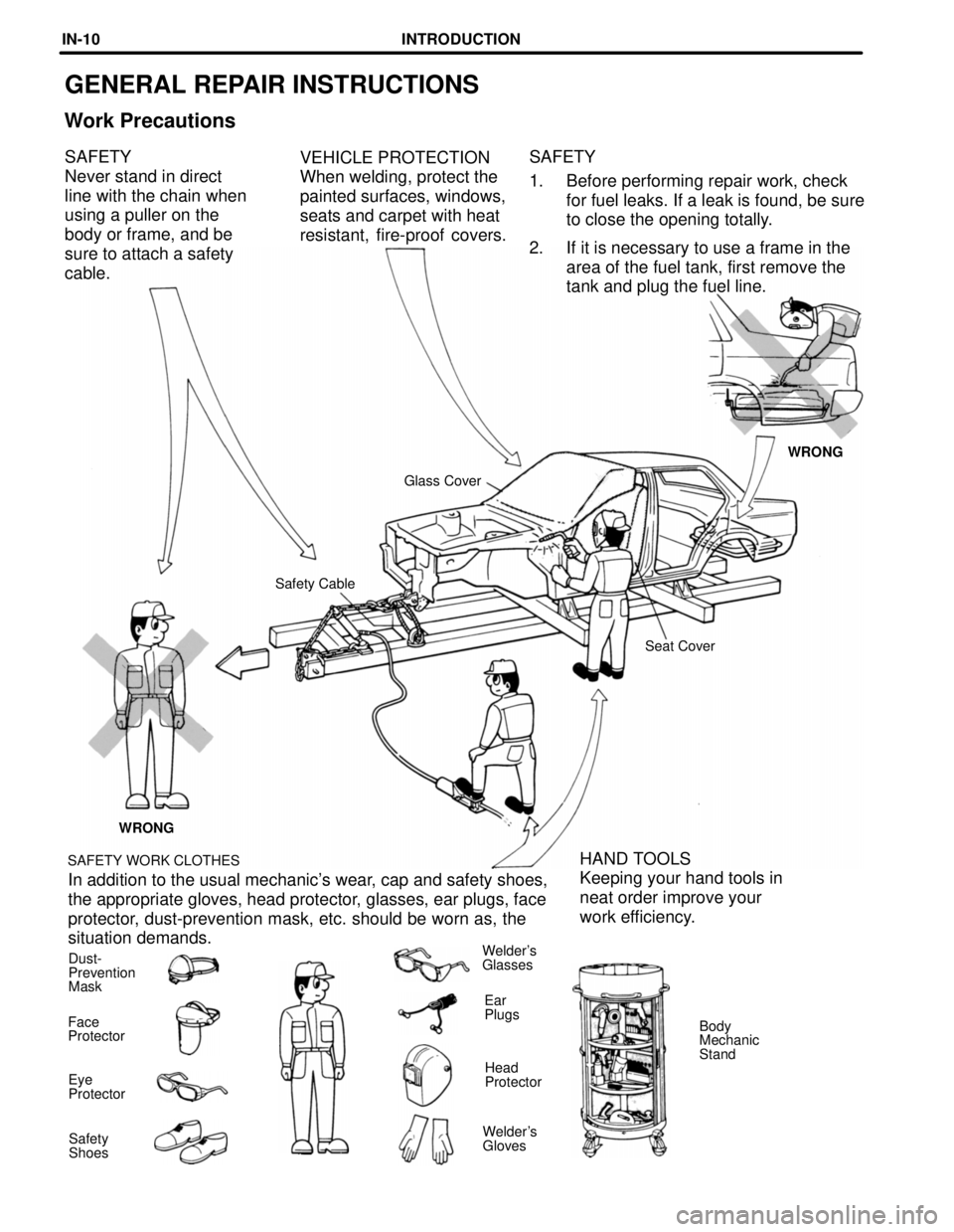
SAFETY
1. Before performing repair work, checkfor fuel leaks. If a leak is found, be sure
to close the opening totally.
2. If it is necessary to use a frame in the area of the fuel tank, first remove the
tank and plug the fuel line.
VEHICLE PROTECTION
When welding, protect the
painted surfaces, windows,
seats and carpet with heat
resistant, fire-proof covers.
SAFETY
Never stand in direct
line with the chain when
using a puller on the
body or frame, and be
sure to attach a safety
cable.
WRONG
Glass Cover
Safety Cable Seat Cover
WRONG
SAFETY WORK CLOTHES
HAND TOOLS
Keeping your hand tools in
neat order improve your
work efficiency.
In addition to the usual mechanic's wear, cap and safety shoes,
the appropriate gloves, head protector, glasses, ear plugs, face
protector, dust-prevention mask, etc. should be worn as, the
situation demands.
Dust-
Prevention
Mask Welder's
Glasses
Ear
Plugs Body
Mechanic
Stand
Face
Protector
Head
Protector
Eye
Protector
Welder's
Gloves
Safety
Shoes
INTRODUCTIONIN-10
WhereEverybodyKnowsYourName
Page 1470 of 4087
(b) Remove the following parts:(1) Spring retainer
(2) Valve spring
(3) Valve
(4) Spring seat
HINT: Arrange the valves, valve springs, spring seats and
spring retainers incorrect order.
(c) Using needle±nose pliers, remove the oil seal.
EG±94
±
1UZ±FE ENGINE ENGINE MECHANICAL
WhereEverybodyKnowsYourName
Page 1476 of 4087

(d) Check the valve overall length.
Standard overall length:Intake94.95 mm (3.7382 in.)
Exhaust 96.90 mm (3.8150 in.)
Minimum overall length:
Intake94.45 mm (3.7185 in.)
Exhaust 96.40 mm (3.7953 in.)
If the overall length is less than minimum, replace the valve.
(e) Check the surface of the valve stem tip for wear. If the valve stem tip is worn, resurface the tip with a grinder
or replace the valve.
NOTICE: Do not grind off more than minimum.
8. INSPECT AND CLEAN VALVE SEATS
(a) Using a 45 � carbide cutter, resurface the valve seats.
Remove only enough metal to clean the seats.
(b) Check the valve seating position. Apply a light coat of prussian blue (or white lead) to the valve
face. Lightly press the valve against the seat. Do not rotate
valve.
(c) Check the valve face and seat for the following: wIf blue appears 360 � around the face, the valve is
concentric. If not, replace the valve.
w If blue appears 360 � around the valve seat, the guide
and face are concentric. If not, resurface the seat.
w Check that the seat contact is in the middle of the valve
face with the following width:
1.0 ± 1.4 mm (0.039 ± 0.055 in.)
If not, correct the valve seats as follows:
(1) If the seating is too high on the valve face, use 30 5 and 45 5
cutters to correct the seat.
EG±100
±
1UZ±FE ENGINE ENGINE MECHANICAL
WhereEverybodyKnowsYourName
Page 1738 of 4087
DISASSEMBLY OF CYLINDER HEAD
(See Components on page EM±35)1. REMOVE VALVE LIFTERS AND SHIMS
HINT: Store the valve lifters and shims in correct order.
2. REMOVE VALVES (a) Using SST, compress the valve spring and remove thetwo keepers.
SST 09202±70010
(b) Remove the spring retainer, valve spring, valve and spring seat.
HINT: Store the valves, valve springs, spring seats and spring
retainers in correct order.
(c) Using needle±nose pliers, remove the oil seal.
±
ENGINE MECHANICAL Cylinder HeadEM±41
WhereEverybodyKnowsYourName
Page 1744 of 4087

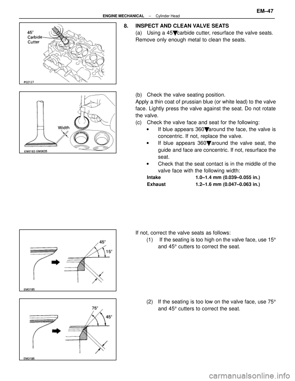
8. INSPECT AND CLEAN VALVE SEATS(a) Using a 45 � carbide cutter, resurface the valve seats.
Remove only enough metal to clean the seats.
(b) Check the valve seating position.
Apply a thin coat of prussian blue (or white lead) to the valve
face. Lightly press the valve against the seat. Do not rotate
the valve.
(c) Check the valve face and seat for the following: w If blue appears 360 � around the face, the valve is
concentric. If not, replace the valve.
w If blue appears 360 � around the valve seat, the
guide and face are concentric. If not, resurface the
seat.
w Check that the seat contact is in the middle of the
valve face with the following width:
Intake 1.0±1.4 mm (0.039±0.055 in.)
Exhaust 1.2±1.6 mm (0.047±0.063 in.)
If not, correct the valve seats as follows:
(1) If the seating is too high on the valve face, use 15 5
and 45 5 cutters to correct the seat.
(2) If the seating is too low on the valve face, use 75 5
and 45 5 cutters to correct the seat.
±
ENGINE MECHANICAL Cylinder HeadEM±47
WhereEverybodyKnowsYourName
Page 1778 of 4087
HINT: Arrange the valve lifters and adjusting shims in correct
order.
2. REMOVE VALVES (a) Using SST, compress the valve spring and remove thetwo keepers.
SST 09202±70010
(b) Remove the following parts: (1) Spring retainer
(2) Valve spring
(3) Valve
(4) Spring seat
HINT: Arrange the valves, valve springs, spring seats and
spring retainers in correct order.
(c) Using needle±nose pliers, remove the oil seal.
±
ENGINE MECHANICAL Cylinder HeadsEM±77
WhereEverybodyKnowsYourName
Page 1784 of 4087

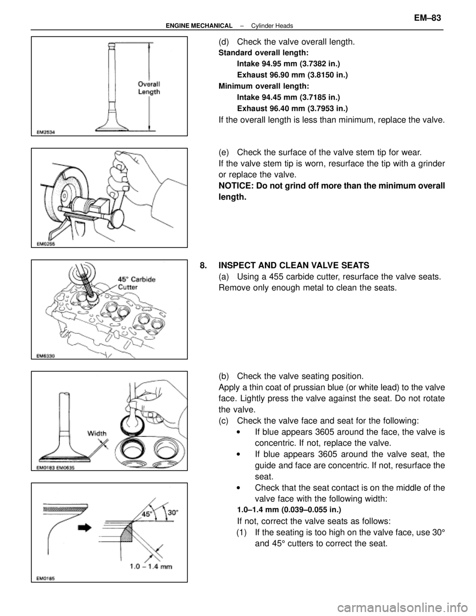
(d) Check the valve overall length.
Standard overall length:Intake 94.95 mm (3.7382 in.)
Exhaust 96.90 mm (3.8150 in.)
Minimum overall length: Intake 94.45 mm (3.7185 in.)
Exhaust 96.40 mm (3.7953 in.)
If the overall length is less than minimum, replace the valve.
(e) Check the surface of the valve stem tip for wear.
If the valve stem tip is worn, resurface the tip with a grinder
or replace the valve.
NOTICE: Do not grind off more than the minimum overall
length.
8. INSPECT AND CLEAN VALVE SEATS (a) Using a 455 carbide cutter, resurface the valve seats.
Remove only enough metal to clean the seats.
(b) Check the valve seating position.
Apply a thin coat of prussian blue (or white lead) to the valve
face. Lightly press the valve against the seat. Do not rotate
the valve.
(c) Check the valve face and seat for the following:w If blue appears 3605 around the face, the valve is
concentric. If not, replace the valve.
w If blue appears 3605 around the valve seat, the
guide and face are concentric. If not, resurface the
seat.
w Check that the seat contact is on the middle of the
valve face with the following width:
1.0±1.4 mm (0.039±0.055 in.)
If not, correct the valve seats as follows:
(1) If the seating is too high on the valve face, use 30 5
and 45 5 cutters to correct the seat.
±
ENGINE MECHANICAL Cylinder HeadsEM±83
WhereEverybodyKnowsYourName
Page 2169 of 4087
26. FINAL INSPECTION
(a) Check the operation of the body parts:wHood:
Auxiliary catch operates properly Hood locks securely
when closed
w Doors:
Door locks operate properly Doors close properly
w Luggage compartment door:
Door lock operates properly
w Seats:
Seat adjusts easily and locks securely in any position
Front seat back locks securely in any position Folding±
down rear seat backs lock securely
(b) Be sure to deliver a clean car. Especially check: wSteering wheel
w Shift lever knob
w All switch knobs
w Seats
MA±18
±
MAINTENANCE (1UZ ± FE)
WhereEverybodyKnowsYourName