Page 24 of 4087
![LEXUS SC400 1991 Service Repair Manual
[2] HEAT METHOD: When the problem seems to occur when the suspect area is heated.
Heat the component that is the likely cause of the malfunc-
tion with a hair dryer or similar object. Check to see if LEXUS SC400 1991 Service Repair Manual
[2] HEAT METHOD: When the problem seems to occur when the suspect area is heated.
Heat the component that is the likely cause of the malfunc-
tion with a hair dryer or similar object. Check to see if](/manual-img/36/57051/w960_57051-23.png)
[2] HEAT METHOD: When the problem seems to occur when the suspect area is heated.
Heat the component that is the likely cause of the malfunc-
tion with a hair dryer or similar object. Check to see if the
malfunction occurs.
NOTICE:
(1) Do not heat to more than 60°C (140 °F).
(Temperature limit that no damage is done to the
component).
(2) Do not apply heat directly to parts in the ECU.
[3] WATER SPRINKLING METHOD: When the malfunction seems to occur on a
rainy\
day or in a high±humidity condition.
Sprinkle w ater onto the vehicle and check to see if the mal-
function occurs.
NOTICE:
(1) Never sprinkle water directly into the engine compartment, but indirectly change the tempera-
ture and humidity by applying water spray onto
the radiator front surface.
(2) Never apply water directly onto the electronic components.
(Service hint)
If a vehicle is subject to water leakage, the leaked water
may contaminate the ECU. When testing a vehicle with a
water leakage problem, special caution must be used.
[4] OTHER: When the malfunction seems to occur when electrical load is excessive.
Turn on all electrical loads including the heater blower,
head lights, rear window defogger, etc. and check to see
if the malfunction occurs.
±
INTRODUCTION TITLE±NAMEIN±21
WhereEverybodyKnowsYourName
Page 118 of 4087
Check power transistor.
(1) Remove cooling unit (See page BO-107).
(2) Disconnect power transistor connector.
(1) Check test bulb lights up when battery and
resistor are connected to power transistor
connector as left illustration shows.
(2) Measure resistance between terminal 2 and 3
(1) The bulb lights up.
(2)Resistance: 2.0± 2.4 ��k �
Replace power transistor.
Check for open and short in harness and connector between air
conditioner control assembly and power transistor (See page IN-27).
Repair or replace harness or connector.
Proceed to next circuit inspection shown on matrix
chart (See page AC-36).
INSPECTION PROCEDURE
±
AIR CONDITIONING SYSTEM TroubleshootingAC±79
WhereEverybodyKnowsYourName
Page 190 of 4087

Diag. Code 22Airbag Warning Light System Malfunction
CIRCUIT DESCRIPTION
The airbag warning light is located on the combination meter.
When the airbag system is normal, the airbag warning light lights up for\
approx. 6 seconds after the
ignition switch is turned from LOCK position to ACC or ON position, and then turns off automatically.
If there is a malfunction in the airbag system, the airbag warning light\
lights up to inform the driver of
the abnormality.
When terminals Tc and E of the TDCL are connected, the diagnostic code is displayed by t\
he blinking
of the airbag warning light.
The airbag warning light circuit is equipped with an electrical connecti\
on check mechanism which
detects when the connector to the center airbag sensor assembly is not p\
roperly connected.
If the connector to the center airbag sensor assembly is not properly co\
nnected, the airbag warning
light will not light up.
Diagnostic code 22 is recorded when a malfunction occurs in the airbag w\
arning light system.
If an OPEN malfunction occurs in the airbag warning light system, the ai\
rbag warning light does not
light up, so that until the malfunction is repaired, the diagnostic code\
s (including code 22) cannot be
confirmed.
Code No.Diagnosis
22� Open circuit in airbag warning light system.22� Center airbag sensor assembly malfunction.
AB±74±
SRS AIRBAG Troubleshooting
WhereEverybodyKnowsYourName
Page 200 of 4087
YES
Does airbag warning light turn off?
NO
1
Replace center airbag sensor assembly. Check airbag warning light circuit
or terminal AB circuit of TDCL or
check connector.
WIRING DIAGRAM
Airbag Warning Light System (Always Lit Up)
CIRCUIT DESCRIPTION
The airbag warning light is located on the combination meter.
When the airbag system is normal, the airbag warning light lights up for\
approx. 6 seconds after the
ignition switch is turned from LOCK position to ACC or ON position, and then turns off automatically.
If there is a malfunction in the airbag system, the airbag warning light\
lights up to inform the driver of
the abnormality.
When terminals Tc and E of the TDCL are connected, the diagnostic code is displayed by t\
he blinking
of the airbag warning light.
DIAGNOSTIC CHART
AB±84±
SRS AIRBAG Troubleshooting
WhereEverybodyKnowsYourName
Page 208 of 4087

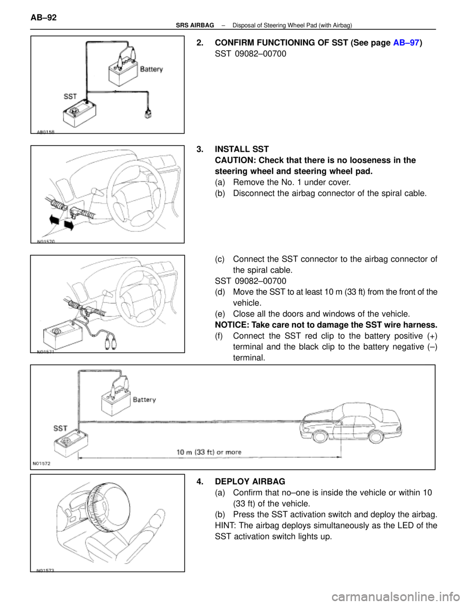
2. CONFIRM FUNCTIONING OF SST (See page AB±97)
SST 09082±00700
3. INSTALL SST CAUTION: Check that there is no looseness in the
steering wheel and steering wheel pad.
(a) Remove the No. 1 under cover.
(b) Disconnect the airbag connector of the spiral cable.
(c) Connect the SST connector to the airbag connector ofthe spiral cable.
SST 09082±00700
(d) Move the SST to at least 10 m (33 ft) from the front of the
vehicle.
(e) Close all the doors and windows of the vehicle.
NOTICE: Take care not to damage the SST wire harness.
(f) Connect the SST red clip to the battery positive (+) terminal and the black clip to the battery negative (±)
terminal.
4. DEPLOY AIRBAG (a) Confirm that no±one is inside the vehicle or within 10 (33 ft) of the vehicle.
(b) Press the SST activation switch and deploy the airbag.
HINT: The airbag deploys simultaneously as the LED of the
SST activation switch lights up.
AB±92
±
SRS AIRBAG Disposal of Steering Wheel Pad (with Airbag)
WhereEverybodyKnowsYourName
Page 212 of 4087

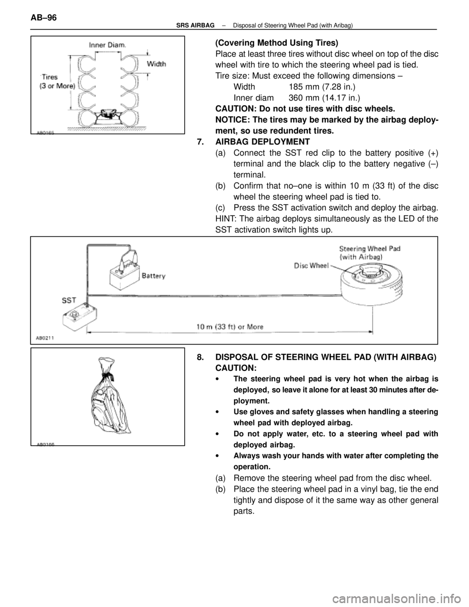
(Covering Method Using Tires)
Place at least three tires without disc wheel on top of the disc
wheel with tire to which the steering wheel pad is tied.
Tire size: Must exceed the following dimensions ±Width 185 mm (7.28 in.)
Inner diam 360 mm (14.17 in.)
CAUTION: Do not use tires with disc wheels.
NOTICE: The tires may be marked by the airbag deploy-
ment, so use redundent tires.
7. AIRBAG DEPLOYMENT (a) Connect the SST red clip to the battery positive (+)terminal and the black clip to the battery negative (±)
terminal.
(b) Confirm that no±one is within 10 m (33 ft) of the disc wheel the steering wheel pad is tied to.
(c) Press the SST activation switch and deploy the airbag.
HINT: The airbag deploys simultaneously as the LED of the
SST activation switch lights up.
8. DISPOSAL OF STEERING WHEEL PAD (WITH AIRBAG) CAUTION:
w The steering wheel pad is very hot when the airbag is
deployed, so leave it alone for at least 30 minutes after de-
ployment.
w Use gloves and safety glasses when handling a steering
wheel pad with deployed airbag.
w Do not apply water, etc. to a steering wheel pad with
deployed airbag.
w Always wash your hands with water after completing the
operation.
(a) Remove the steering wheel pad from the disc wheel.
(b) Place the steering wheel pad in a vinyl bag, tie the end
tightly and dispose of it the same way as other general
parts.
AB±96
±
SRS AIRBAG Disposal of Steering Wheel Pad (with Aribag)
WhereEverybodyKnowsYourName
Page 213 of 4087
CONFIRM FUNCTIONING OF SST
When deploying the airbag, always use the specified SST:
SRS AIRBAG DEPLOYMENT TOOL.
SST 09082±00700
1. CONNECT SST TO BATTERY Connect the red clip of the SST to the battery positive (+) ter-
minal and the black clip to the battery negative (±) terminal.
HINT: Do not connect the yellow connector which connects
with the airbag system.
2. CONFIRM FUNCTIONING OF SST Press the SST activation switch, and confirm the LED of the
SST activation switch lights up.
CAUTION: If the LED lights up when the activation switch
is not being pressed, SST malfunction is probable, so
definitely do not use the SST.
±
SRS AIRBAG Disposal of Steering Wheel Pad (with Aribag)AB±97
WhereEverybodyKnowsYourName
Page 243 of 4087

Customer Problem Analysis Check Sheet
SRS AIRBAG System Check Sheet
Registration No.
Customer 's NameRegistration Year/ /
Frame No.
Date Vehicle
Brought In/ /Odometer ReadingKm
Miles
Date of Problem Occurrence / /
Weather�Fine �Cloudy �Rainy �Snowy �Various/Other
Conditions
Outdoor
Temperature�Hot �Warm �Cool �Cold (Approx. �C ( �F))
Conditions
at Time
of Problem
OccurrenceVehicle
Operation
� Starting �Idling
� Driving
� Constant speed �Acceleration �Deceleration �Other]
[
Condition
of road
Details of Problem
Vehicle Inspection,
Repair History Prior
to Occurrence of
Malfunction
(Including Airbag
System)
(Diagnosis System Inspection)
Airba
g Warning1st Time� Remain On �Sometimes Lights Up �Does Not Light UpAirbag Warning
Light Inspection2nd Time�Remain On �Sometimes Lights Up �Does Not Light Up
Diagnostic Code1st Time�Normal Code �Malfunction Code [Code. ]Diagnostic Code
Inspection2nd Time�Normal Code �Malfunction Code [Code. ]
AB±29SRS AIRBAG ± Troubleshooting
Inspector 's
Name:
WhereEverybodyKnowsYourName