Page 538 of 4087

( Coolant Level Warning Switch)
REMOVAL AND INSTALLATION OF COOLANT
LEVEL WARNING SWITCH
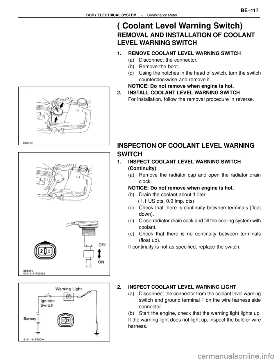
1. REMOVE COOLANT LEVEL WARNING SWITCH(a) Disconnect the connector.
(b) Remove the boot.
(c) Using the notches in the head of switch, turn the switchcounterclockwise and remove it.
NOTICE: Do not remove when engine is hot.
2. INSTALL COOLANT LEVEL WARNING SWITCH For installation, follow the removal procedure in reverse.
INSPECTION OF COOLANT LEVEL WARNING
SWITCH
1. INSPECT COOLANT LEVEL WARNING SWITCH(Continuity)
(a) Remove the radiator cap and open the radiator drainclock.
NOTICE: Do not remove when engine is hot.
(b) Drain the coolant about 1 liter. (1.1 US qts, 0.9 lmp. qts)
(c) Check that there is continuity between terminals (float down).
(d) Close radiator drain cock and fill the cooling system with
coolant.
(e) Check that there is no continuity between terminals (float up).
If continuity is not as specified, replace the switch.
2. INSPECT COOLANT LEVEL WARNING LIGHT (a) Disconnect the connector from the coolant level warning
switch and ground terminal 1 on the wire harness side
connector.
(b) Start the engine, check that the warning light lights up.
If the warning light does not light up, inspect the bulb or wire
harness.
±
BODY ELECTRICAL SYSTEM Combination MeterBE±117
WhereEverybodyKnowsYourName
Page 592 of 4087

Parts Inspection
(Power Switch)
REMOVAL AND INSTALLATION OF
POWER SWITCH
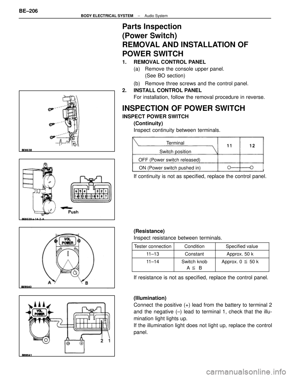
1. REMOVAL CONTROL PANEL(a) Remove the console upper panel.(See BO section)
(b) Remove three screws and the control panel.
2. INSTALL CONTROL PANEL For installation, follow the removal procedure in reverse.
INSPECTION OF POWER SWITCH
INSPECT POWER SWITCH
(Continuity)
Inspect continuity between terminals.
Terminal
Switch position
OFF (Power switch released) ON (Power switch pushed in)
If continuity is not as specified, replace the control panel.
(Resistance)
Inspect resistance between terminals.
Tester connectionConditionSpecified value
11±13ConstantApprox. 50 k �
11±14Switch knob
A � BApprox. 0 � 50 k �
If resistance is not as specified, replace the control panel.
(Illumination)
Connect the positive (+) lead from the battery to terminal 2
and the negative (±) lead to terminal 1, check that the illu-
mination light lights up.
If the illumination light does not light up, replace the control
panel.
BE±206
±
BODY ELECTRICAL SYSTEM Audio System
WhereEverybodyKnowsYourName
Page 684 of 4087
OKNG
NGOK
INSPECTION PROCEDURE
1Check the shift position indicator.
Check that P lights up on the shift indicator when P range is shifted in\
to, and that P is OFF when
shiftin
g into another range.
C
Check shift position indicator circuit (See page BE±141).
2Check voltage between terminal P of ECU connector and body ground.
C
OK
PRemove ECU with connectors still connected.
(1) Turn ignition switch ON.
(2) Measure voltage between terminal P of ECU con-nector and body ground when the shift lever is posi-
tioned to the following ranges.
Shift range
P
1
0
Other than PVoltage
10 ± 14 V
Below 1 V
Proceed to next circuit inspection shown on matrix chart
(See page BE±276).
Check and repair harness and connector between
ECU and connector.
±
BODY ELECTRICAL SYSTEM Power Seat Control System (Driver's Seat)BE±301
WhereEverybodyKnowsYourName
Page 801 of 4087

Check for Voltage
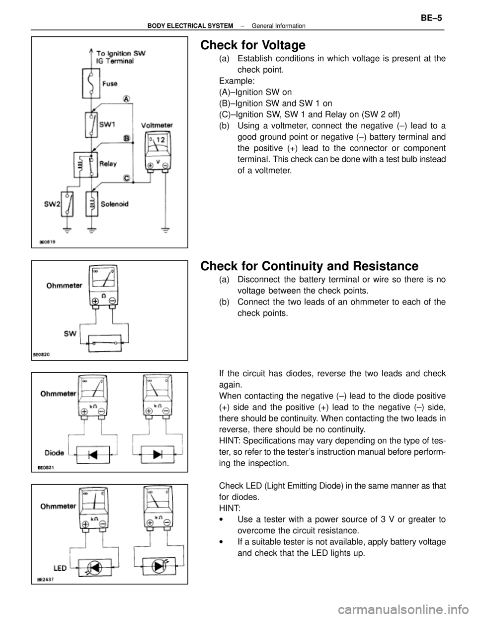
(a) Establish conditions in which voltage is present at thecheck point.
Example:
(A)±Ignition SW on
(B)±Ignition SW and SW 1 on
(C)±Ignition SW, SW 1 and Relay on (SW 2 off)
(b) Using a voltmeter, connect the negative (±) lead to a good ground point or negative (±) battery terminal and
the positive (+) lead to the connector or component
terminal. This check can be done with a test bulb instead
of a voltmeter.
Check for Continuity and Resistance
(a) Disconnect the battery terminal or wire so there is no voltage between the check points.
(b) Connect the two leads of an ohmmeter to each of the check points.
If the circuit has diodes, reverse the two leads and check
again.
When contacting the negative (±) lead to the diode positive
(+) side and the positive (+) lead to the negative (±) side,
there should be continuity. When contacting the two leads in
reverse, there should be no continuity.
HINT: Specifications may vary depending on the type of tes-
ter, so refer to the tester's instruction manual before perform-
ing the inspection.
Check LED (Light Emitting Diode) in the same manner as that
for diodes.
HINT:
w Use a tester with a power source of 3 V or greater to
overcome the circuit resistance.
w If a suitable tester is not available, apply battery voltage
and check that the LED lights up.
±
BODY ELECTRICAL SYSTEM General InformationBE±5
WhereEverybodyKnowsYourName
Page 804 of 4087
PREPARATION
SST (SPECIAL SERVICE TOOLS)
IllustrationPart No.Part NameNote
09213±31021
Crankshaft Pulley
Puller
For removing steering wheel
RECOMMENDED TOOLS
IllustrationPart No.Part NameNote
09082±00015TOYOTA
Electrical Tester
09041±0030Torx Driver
T30
For removing and installing steering wheel pad and
power window motor
09042±00010Torx Socket
T30For removing and installing steering wheel pad and
power window motor
EQUIPMENT
Part NameNote
Voltmeter
Ammeter
Ohmmeter
Test lead
ThermometerWater temperature sender gauge, Engine oil level, Warning switch, Seat heater
SyphonBrake fluid level warning switch
Oil bathEngine oil level warning switch
Bulb (1.4 W)Coolant level warning ECU
Bulb (3.4 W)Fuel sender, gauge, Seat belt warning relay
Bulb (21 W)Turn signal flasher relay
Dry cell batteryFuel sender gauge
Heat lightSeat heater
Hexagon wrench (6 mm)Power seat
BE±8±
BODY ELECTRICAL SYSTEM Preparation
WhereEverybodyKnowsYourName
Page 825 of 4087

(HEADLIGHT SYSTEM)
Description ± Headlight System
The component parts of this system and their function are described in the \
following table.
Parts NameFunction
Light Control SwitchGrounds current from the headlight control relay and taillight control r\
elay via the
integration relay, switching each relay and supplying current to the appropriate bulbs
accordance with the switch position.
Dimmer SwitchGrounds current from the dimmer relay in accordance with the switch posi\
tion, turning
on the ºLO±Beamº or ºHI Beamº lights. In the case of º\
FLASHº it turns the heading
control relay and turns on the ºHI Beamº lights.
Headlight Control
RelayTurned on by signals from the light control switch, dimmer switch and run\
ning light
relay and supplies current to each bulb or headlight dimmer relay.
Headlight
Dimmer RelayReceives current from the headlight control relay, which switches the relay according
to the position of the dimmer switch and sends current to the headlight \
ºLO±Beamº
or ºHI Beamº.
Integration RelayCarries out ºLight Auto Turn±offº of the headlights and taillights and cuts off current to
the light control switch in accordance with signals from the GAUGE fuse \
and courtesy
switch.
Door Courtesy
Switch/Driver 'sDetects when the door is open and sends the appropriate signals to integ\
ration relay.
(Light Auto Turn±Off System)
Parking Brake
Switch
(CANADA)Detects when the parking brake lever is released and sends the appropria\
te signals to
daytime running light relay.
±
BODY ELECTRICAL SYSTEM Lighting SystemBE±29
WhereEverybodyKnowsYourName
Page 826 of 4087
System Description ± Headlights
DAYTIME RUNNING LIGHT SYSTEM
The Daytime Running Light (DRL) system is activated when engine is started (However, if the parking brake
lever is engaged when the engine is started, the DRL will not light up a\
fter the engine has started. Once the
parking brake is released, the DRL will then light up and will remain on regardless of operation of\
the parking
brake lever).
The DRL remain on until the ignition switch is turned off.
BE±30±
BODY ELECTRICAL SYSTEM Lighting System
WhereEverybodyKnowsYourName
Page 827 of 4087
Operation example (Current flow table)
1. Daytime Running Light Lights Up
SwitchPosition
Ignition switchON (Engine running)
Light Control SwitchOFF
Headlight Dimmer SwitchLO or HI
Condition: Battery Voltage " (3) , (14)
2. Taillight Lights Up
SwitchPosition
Ignition SwitchOFF or ON
Light Control SwitchTAIL
Headlight Dimmer SwitchLO or HI
Condition: Battery Voltage " (3)
Continuity (16) " (17) " Ground
3. Headlight LO±Beam Lights Up
SwitchPosition
Ignition SwitchOFF or ON
Light Control SwitchHEAD
Headlight Dimmer SwitchLO
Condition: Battery Voltage " (3)
Continuity (16) " (17) " Ground
(18) " (17) " Ground
±
BODY ELECTRICAL SYSTEM Lighting SystemBE±31
WhereEverybodyKnowsYourName