Page 828 of 4087
4. Headlight HI±Beam Lights Up
SwitchPosition
Ignition SwitchOFF or ON
Light Control SwitchHEAD
Headlight Dimmer SwitchHI
Condition: Battery Voltage " (3)
Continuity (20) " (21) " Ground
(18) " (17) " Ground
(16) " (17) " Ground
5. Headlight Flash
SwitchPosition
Ignition SwitchOFF or ON
Light Control SwitchOFF or TAIL or HEAD
Headlight Dimmer SwitchFLASH
Condition: Battery Voltage " (3)
Continuity (19) " (21) " Ground
(20) " (21) " Ground
BE±32±
BODY ELECTRICAL SYSTEM Lighting System
WhereEverybodyKnowsYourName
Page 832 of 4087
Connector Diagrams ± Headlights
BE±36±
BODY ELECTRICAL SYSTEM Lighting System
WhereEverybodyKnowsYourName
Page 834 of 4087

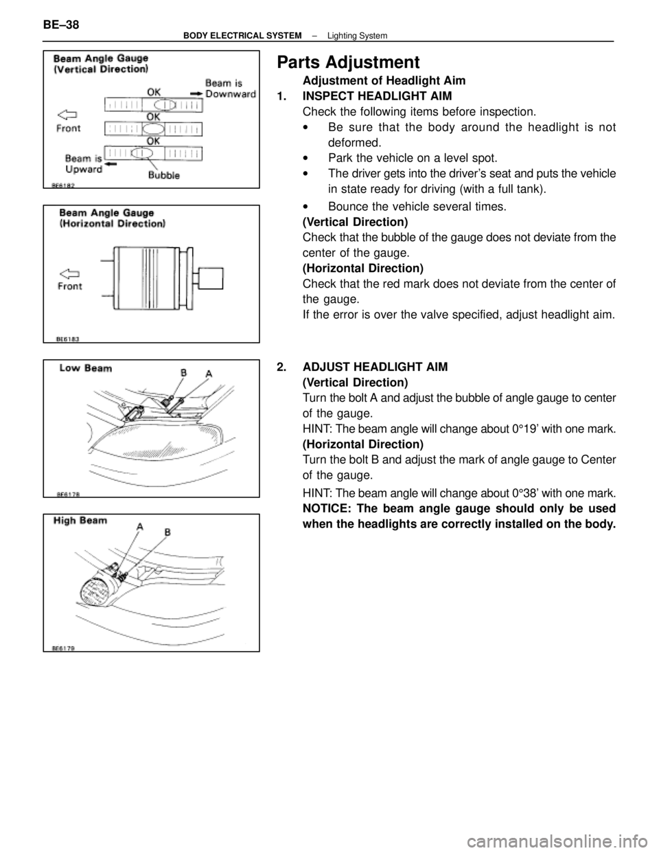
Parts Adjustment
Adjustment of Headlight Aim
1. INSPECT HEADLIGHT AIM Check the following items before inspection.
wBe sure that the body around the headlight is not
deformed.
w Park the vehicle on a level spot.
w The driver gets into the driver's seat and puts the vehicle
in state ready for driving (with a full tank).
w Bounce the vehicle several times.
(Vertical Direction)
Check that the bubble of the gauge does not deviate from the
center of the gauge.
(Horizontal Direction)
Check that the red mark does not deviate from the center of
the gauge.
If the error is over the valve specified, adjust headlight aim.
2. ADJUST HEADLIGHT AIM (Vertical Direction)
Turn the bolt A and adjust the bubble of angle gauge to center
of the gauge.
HINT: The beam angle will change about 0 519' with one mark.
(Horizontal Direction)
Turn the bolt B and adjust the mark of angle gauge to Center
of the gauge.
HINT: The beam angle will change about 0 538' with one mark.
NOTICE: The beam angle gauge should only be used
when the headlights are correctly installed on the body.
BE±38
±
BODY ELECTRICAL SYSTEM Lighting System
WhereEverybodyKnowsYourName
Page 852 of 4087

(TAILLIGHT SYSTEM)
Description ± Taillight System
The component parts of this system and their function are as shown in the f\
ollowing table.
�������� ��������Parts Name������������������\
����������� ������������������\
�����������Function
�������� �
�������
��������
Light Control Switch������������������\
����������� �
������������������\
����������
������������������\
�����������
Grounds current from the taillight control relay via the integration rel\
ay, switching each relay
and supplying current to the appropriate bulbs accordance with the switc\
h position.
�������� ��������Taillight Control Relay������������������\
����������� ������������������\
�����������Turned on by signals from the light control switch and supplies current t\
o each bulb.
�������� �
�������
�
�������
��������
Integration Relay
������������������\
����������� �
������������������\
����������
�
������������������\
����������
������������������\
�����������
Carries out ºLight Auto Turn±Offº of the headlights, fog lights and taillights and cuts off cur-
rent to the light control switch in accordance with signals from the GAU\
GE fuse and door
courtesy switch.
�������� �
�������
��������
Light Failure Sensor������������������\
����������� �
������������������\
����������
������������������\
�����������
This sensor senses when a bulb in rear combination light is burnt out an\
d lights up a warning
light.
��������Integration Relay������������������\
������������������� ��������Integration Relay
(Daytime Running
������������������\
����������� ������������������\
�����������
Refer to
BE±30.�������� ��������(y g
Light Relay: CANADA)������������������\
����������� ������������������\
�����������
PARTS LOCATION ± Taillight System
±
BODY ELECTRICAL SYSTEM Lighting SystemBE±53
WhereEverybodyKnowsYourName
Page 854 of 4087

Parts Replacement ± Taillights
(Clearance Light)
REPLACEMENT OF CLEARANCE LIGHT
(See page BE±37)
HINT: Replacement of Headlight (LO±Beam).
(FRONT SIDE MARKER LIGHT)
REPLACEMENT OF FRONT SIDE
MARKER LIGHT
1. REMOVE FRONT SIDE MARKER LIGHT (a) Disconnect negative (±) terminal from the battery.
CAUTION: Work must be started after approx.20
seconds from the time the ignition switch is turned to the
ºLOCKº position and negative (±) terminal cable is
disconnected from the battery.
(b) Remove fender liner. BO±92)
(c) Remove two nuts.
(d) Remove front side marker light from bumper.
(e) Disconnect connector.
2. INSTALL FRONT SIDE MARKER LIGHT For installation, follow the removal procedure in reverse.
(Light Failure Sensor)
See page BE±62
(Integration Relay)
See page BE±49
(Rear Combination Assembly)
REPLACEMENT OF REAR
COMBINATION LIGHT ASSEMBLY
1. REMOVE REAR COMBINATION LIGHT ASSEMBLY
(a)Disconnect negative (±) terminal from the battery.
CAUTION: Work must be started after approx. 20
seconds from the time the ignition switch is turned to the
ºLOCKº position and negative (±) terminal cable is
disconnected from the battery.
±
BODY ELECTRICAL SYSTEM Lighting SystemBE±55
WhereEverybodyKnowsYourName
Page 856 of 4087
Parts Inspection ± Taillights
(Combination Switch Assembly)
(See page BE±46
HINT: Inspect light control switch.
(Taillight Control Relay)
REMOVAL AND INSTALLATION OF
TAILLIGHT CONTROL RELAY
(See page BE±16)
INSPECTION OF TAILLIGHT CONTROL
RELAY
INSPECT TAILLIGHT CONTROL RELAY
(Continuity)
Inspect relay continuity between terminals.
If continuity is not as specified, replace the relay.
(Relay Circuit)
(See page BE±20)
±
BODY ELECTRICAL SYSTEM Lighting SystemBE±57
WhereEverybodyKnowsYourName
Page 858 of 4087
(STOP LIGHT SYSTEM)
DESCRIPTION ± Stoplight System
The component parts of this system and their function are as shown in the f\
ollowing table.
������� �������Parts Name������������������\
������������ ������������������\
������������Function
������� �
������
�������Stop Light Switch
������������������\
������������ �
������������������\
�����������
������������������\
������������
Creates a closed circuit for current from the STOP fuse when the brake pedal is depressed,
thus turning on the stop lights.
������� �
������
�������
Light Failure Sen-
sor������������������\
������������ �
������������������\
�����������
������������������\
������������
This sensor senses when a bulb in rear combination light is burnt out an\
d lights up a warning
light.
PARTS LOCATION ± Stoplight System
±
BODY ELECTRICAL SYSTEM Lighting SystemBE±59
WhereEverybodyKnowsYourName
Page 860 of 4087

Parts Replacement ± Stoplights
(Rear Combination Light)
(See page BE±56 )
(High Mount Stop Light)
REPLACEMENT OF HIGH MOUNT STOP
LIGHT
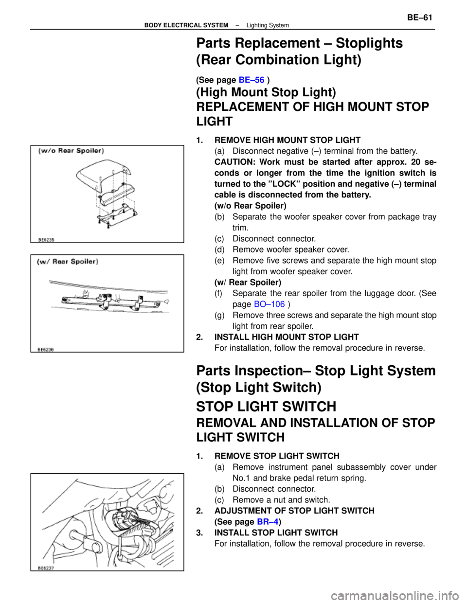
1. REMOVE HIGH MOUNT STOP LIGHT
(a) Disconnect negative (±) terminal from the battery.
CAUTION: Work must be started after approx. 20 se-
conds or longer from the time the ignition switch is
turned to the ºLOCKº position and negative (±) terminal
cable is disconnected from the battery.
(w/o Rear Spoiler)
(b) Separate the woofer speaker cover from package tray
trim.
(c) Disconnect connector.
(d) Remove woofer speaker cover.
(e) Remove five screws and separate the high mount stop light from woofer speaker cover.
(w/ Rear Spoiler)
(f) Separate the rear spoiler from the luggage door. (See page BO±106 )
(g) Remove three screws and separate the high mount stop
light from rear spoiler.
2. INSTALL HIGH MOUNT STOP LIGHT For installation, follow the removal procedure in reverse.
Parts Inspection± Stop Light System
(Stop Light Switch)
STOP LIGHT SWITCH
REMOVAL AND INSTALLATION OF STOP
LIGHT SWITCH
1. REMOVE STOP LIGHT SWITCH
(a) Remove instrument panel subassembly cover underNo.1 and brake pedal return spring.
(b) Disconnect connector.
(c) Remove a nut and switch.
2. ADJUSTMENT OF STOP LIGHT SWITCH (See page BR±4)
3. INSTALL STOP LIGHT SWITCH For installation, follow the removal procedure in reverse.
±
BODY ELECTRICAL SYSTEM Lighting SystemBE±61
WhereEverybodyKnowsYourName