1991 LEXUS SC400 lights
[x] Cancel search: lightsPage 2772 of 4087

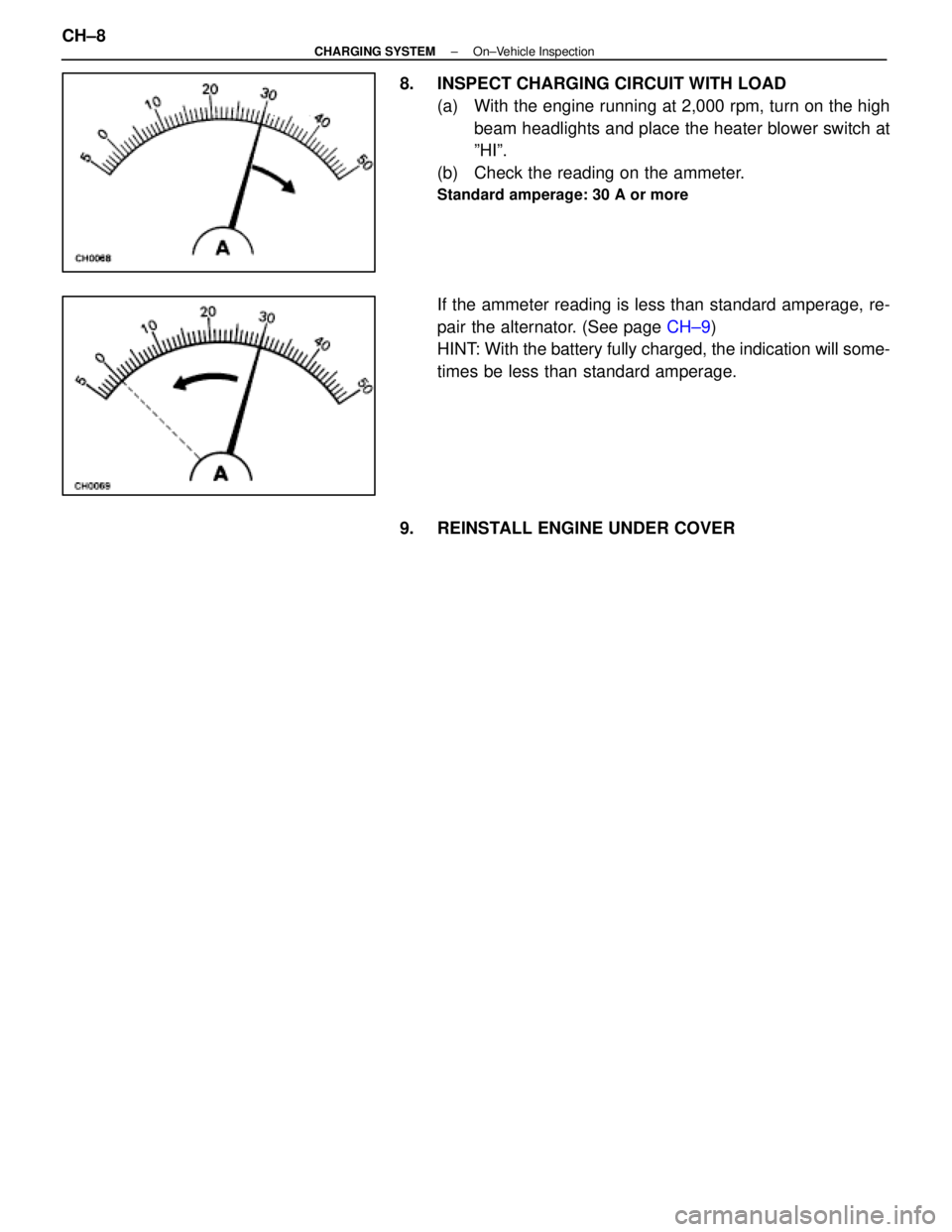
8. INSPECT CHARGING CIRCUIT WITH LOAD(a) With the engine running at 2,000 rpm, turn on the highbeam headlights and place the heater blower switch at
ºHIº.
(b) Check the reading on the ammeter.
Standard amperage: 30 A or more
If the ammeter reading is less than standard amperage, re-
pair the alternator. (See page CH±9)
HINT: With the battery fully charged, the indication will some-
times be less than standard amperage.
9. REINSTALL ENGINE UNDER COVER
CH±8
±
CHARGING SYSTEM On±Vehicle Inspection
WhereEverybodyKnowsYourName
Page 2886 of 4087

The 1 UZ±FE engine has 8±cylinders in a V±arrangement at a bank an\
gle of 905. From the front of the RH
bank cylinders are numbered 2±4±6±8, and from the front of the LH b\
ank cylinders are numbered 1 ±3±5±7.
The crankshaft is supported by 5 bearings specified by the inside of the cr\
ankcase. These bearings are made
of a copper and lead alloy. The crankshaft is integrated with 8 weights which are cast along with it\
for balancing. Oil holes are built
into the center of the crankshaft for supplying oil to the connecting ro\
ds, pistons and other components. The ignition order is 1±8±4±3±6±5±7±2. The cylinder\
head is made of aluminum alloy, with a cross flow
type intake and exhaust layout and with pent±roof type combustion chambers. The spark plugs are loca\
ted in
the center of the combustion chambers.
At the front and rear of the intake manifold, a water passage has been p\
rovided which connects the RH
and LH cylinder heads. Exhaust and intake valves are equipped with irregular pitch springs made\
of special valve spring carbon
steel which are capable of following no matter what the engine speed.
The RH and LH intake camshafts are driven by a single timing belt, and a ge\
ar on the intake camshaft en-
gages with a gear on the exhaust camshaft to drive it. The camshaft jour\
nal is supported at 5 (intake) or 4 (ex-
haust) places between the valve lifters of each cylinder and on the front end of the cylinder \
head. Lubrication
of the cam journal gear is accomplished by oil being supplied through the \
oiler port in the center of the camshaft. Adjustment of the valve clearance is done by means of an outer shim type\
system, in which valve adjusting
shims are located above the valve lifters. This permits replacement of the sh\
ims without removal of the cam-
shafts. Pistons are made of high temperature±resistant aluminum alloy, and a depression is built into the piston
head to prevent interference with valves.
Piston pins are the full±floating type, with the pins fastened to neither the piston boss nor the connecting
rods. Instead, snap rings are fitted on both ends of the pins, preventing the\
pins from falling out. The No.1 compression ring is made of steel and the No.2 compression ring\
is made of cast iron. The oil
ring is m ade of a combination of steel and stainless steel. The outer diameter of\
each piston ring is slightly larger
than the diameter of the piston and the flexibility of the rings allows them\
to hug the cylinder walls when they
are mounted on the piston. Compression rings No.1 and No.2 work to prevent \
the leakage of gas from the cylin-
der and the oil ring works to scrape oil off the cylinder walls to prevent it from entering the combustion chamber. The cylinder block is made of aluminum alloy with a bank angle of 90 5. Cast iron cylinders are installed
inside the cylinder block. It has 8 cylinders which are approximately twice the length of th\
e piston stroke. The
top of each cylinder is closed off by the cylinder heads and the lower end of the cylinders becomes the crank-
case, in which the crankshaft is installed. In addition, the cylinder bl\
ock contains a water jacket, through which
coolant is pumped to cool the cylinders. The No.1 and No.2 oil pans are bolted onto the bottom of the cylinder block\
. The No.1 oil pan is made of
aluminum alloy. The No.2 oil pan is an oil reservoir made of pressed steel sheet. An o\
il level sensor is installed
in the No.1 oil pan (If the oil level drops below a set level, a warnin\
g light lights up.). A oil pan baffle plate keeps
sufficient oil in the bottom of the No.2 oil pan even when the vehicle is tilted. \
This dividing plate also prevents
the oil from making waves when the vehicle is stopped suddenly and the oil \
shifts away from the oil pump suction
pipe. Plastic region tightening bolts are used for the cylinder head, main bearing ca\
p and connecting rod.
EM±4
±
ENGINE MECHANICAL Operation
WhereEverybodyKnowsYourName
Page 2955 of 4087

OKNG
NGOK
INSPECTION PROCEDURE
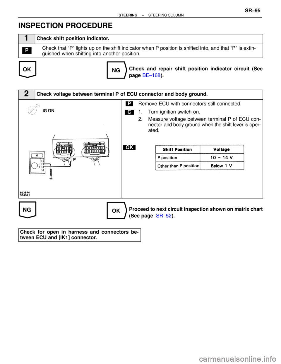
1Check shift position indicator.
Check that ªPº lights up on the shift indicator when P position is shif\
ted into, and that ªPº is extin-
guished when shifting into another position.P
Check and repair shift position indicator circuit (See
page BE±168 ).
2Check voltage between terminal P of ECU connector and body ground.
C
OK
PRemove ECU with connectors still connected.
1. Turn ignition switch on.
2. Measure voltage between terminal P of ECU con-
nector and body ground when the shift lever is oper-
ated.
Proceed to next circuit inspection shown on matrix chart
(See page SR±52).
Check for open in harness and connectors be-
tween ECU and [IK1] connector.
±
STEERING STEERING COLUMNSR±95
WhereEverybodyKnowsYourName
Page 3097 of 4087

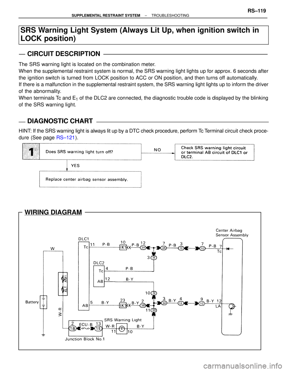
WIRING DIAGRAM
SRS Warning Light System (Always Lit Up, when ignition switch in
LOCK position)
CIRCUIT DESCRIPTION
The SRS warning light is located on the combination meter.
When the supplemental restraint system is normal, the SRS warning light ligh\
ts up for approx. 6 seconds after
the ignition switch is turned from LOCK position to ACC or ON position, and\
then turns off automatically.
If there is a malfunction in the supplemental restraint system, the SRS wa\
rning light lights up to inform the driver
of the abnormality.
When terminals Tc and E
1 of the DLC2 are connected, the diagnostic trouble code is displayed by \
the blinking
of the SRS warning light.
DIAGNOSTIC CHARTDIAGNOSTIC CHART
HINT: If the SRS warning light is always lit up by a DTC check procedure, per\
form Tc T erminal circuit check proce-
dure (See page RS±121).
±
SUPPLEMENTAL RESTRAINT SYSTEM TROUBLESHOOTINGRS±119
WhereEverybodyKnowsYourName
Page 3127 of 4087

4. DEPLOY AIRBAG
(a) Confirm that no±one is inside the vehicle or within 10 m (33ft) of the vehicle.
(b) Press the SST activation switch and deploy the airbag. HINT: The airbag deploys simultaneously as the LED of the
SST activation switch lights up.
5. DISPOSAL OF STEERING WHEEL PAD (WITH AIRBAG)
CAUTION:
w The steering wheel pad is very hot when the airbag is
deployed, so leave it alone for at least 30 minutes after
deployment.
w Use gloves and safety glasses when handling a steering
wheel pad with deployed airbag.
w Do not apply water, etc. to a steering wheel pad with
deployed airbag.
w Always wash your hands with water after completing the
operation.
(a) When scrapping a vehicle, deploy the airbag and scrap the
vehicle with the steering wheel pad still installed.
(b) When moving a vehicle for scrapping which has a steering
wheel pad with deployed airbag, use gloves and safety
glasses.
When disposing of the steering wheel
pad only
When disposing of the steering wheel pad (with airbag)
only, never use the customer's vehicle to deploy the air-
bag.
Remove the steering wheel pad from the vehicle and be sure
to follow the procedure given below when deploying the air-
bag.
HINT: Have a battery ready as the power source deploy the
airbag.
1. REMOVE STEERING WHEEL PAD (See page RS±18)
CAUTION:
w When removing the steering wheel pad (with airbag),
work must be started after 90 seconds from the time the
ignition switch is turned to the LOCK position and the
negative (±) terminal cable is disconnected from the
battery.
w When storing the steering wheel pad, keep the upper
surface of the pad facing upward.
±
SUPPLEMENTAL RESTRAINT SYSTEM STEERING WHEEL PAD AND SPIRAL CABLERS±23
WhereEverybodyKnowsYourName
Page 3130 of 4087

6. COVER STEERING WHEEL PAD WITH CARDBOARDBOX OR TIRES
Covering Method Using Cardboard Box:
Cover the steering wheel pad with the cardboard box and
weigh the cardboard box down in four places with a at least
196 N (20 kgf, 44 lbf).
Size of cardboard box:
Must exceed the following dimensions±
x = 460 mm (18.11 in.) When dimension y of the cardboard box exceeds the
diameter of the disc wheel with tire the steering wheel
pad is tied to±
x = 460 mm (18.11 in.) + width of tire
y = 650 mm (25.59 in.)
NOTICE: If a cardboard box smaller than the size speci-
fied is used, the cardboard box will be broken by the
shock of the airbag deployment.
Covering Method Using Tires:
Place at least 3 tires without disc wheel on top of the disc
wheel with tire to which the steering wheel pad is tied.
Tire size: Must exceed the following dimensions± Width 185 mm (7.28 in.)
Inner diam 360 mm (14.17 in.)
CAUTION: Do not use tires with disc wheels.
NOTICE: The tires by marked by the airbag deployment,
so use redundant tires.
7. AIRBAG DEPLOYMENT
(a) Connect the SST red clip to the battery positive (+) terminal and the black clip to the battery negative (±) terminal.
(b) Confirm that no±one is within 10 m (33 ft) of the disc wheel the steering wheel pad is tied to.
(c) Press the SST activation switch and deploy the airbag. HINT: The airbag deploys simultaneously as the LED of the
SST activation switch lights up.
RS±26±
SUPPLEMENTAL RESTRAINT SYSTEM STEERING WHEEL PAD AND SPIRAL CABLE
WhereEverybodyKnowsYourName
Page 3131 of 4087

8. DISPOSAL OF STEERING WHEEL PAD (WITH AIRBAG)CAUTION:
w The steering wheel pad is battery hot when the airbag is
deployed, so leave it alone for at least 30 minutes after
deployment.
w Use gloves and safety glasses when handling a steering
wheel pad with deployed airbag.
w Do not apply water, etc. to a steering wheel pad with
deployed airbag.
w Always wash your hands with water after completing the
operation.
(a) Remove the steering wheel pad from the disc wheel.
(b) Place the steering wheel pad in a vinyl bag, tie the end tightly
and dispose of it the same way as other general parts.
CONFIRM FUNCTIONING OF SST
RS014±02
When deploying the airbag, always use the specified SST:
SRS AIRBAG DEPLOYMENT TOOL.
SST 09082±00700
1. CONNECT SST TO BATTERY Connect the red clip of the SST to the battery positive (+) ter-
minal and the black clip to the battery negative (±) terminal.
HINT: Do not connect the yellow connector which connects
with the supplemental restraint system.
2. CONFIRM FUNCTIONING OF SST Press the SST activation switch, and confirm the LED of the
SST activation switch lights up.
CAUTION: If the LED lights up when the activation switch
is not being pressed, SST malfunction is probable, so
definitely do not use the SST.
±
SUPPLEMENTAL RESTRAINT SYSTEM STEERING WHEEL PAD AND SPIRAL CABLERS±27
WhereEverybodyKnowsYourName
Page 3140 of 4087

(b) Move the SST to at least 10 m (33 ft) from the front of thevehicle.
(c) Close all the doors and windows of the vehicle. NOTICE: Take care not change the SST wire harness.
(d) Connect the SST red clip to the battery positive (+) terminal and the black clip to the battery negative (±) terminal.
5. DEPLOY AIRBAG
(a) Confirm that no±one is inside the vehicle or within 10 m (33ft) of the vehicle.
(b) Press the SST activation switch and deploy the airbag. HINT: The airbag deploys simultaneously as the LED of the
SST activation switch lights up.
6. DISPOSAL OF FRONT PASSENGER AIRBAG ASSEMBLY
NOTICE:
w The front passenger airbag assembly is very out not
when the airbag is deployed, so leave it alone for at least
30 minutes after deployment.
w Use gloves and safety glasses when handling a front
passenger airbag assembly with deployed airbag.
w Do not apply water, etc., to a front passenger airbag
assembly with deployed airbag.
w Always wash your hands with water after completing the
operation.
When scrapping a vehicle, deploy the airbag and scrap the
vehicle with the front passenger airbag assembly still
installed.
RS±36
±
SUPPLEMENTAL RESTRAINT SYSTEM FRONT PASSENGER AIRBAG ASSEMBLY
WhereEverybodyKnowsYourName