Page 41 of 4087

R±12 AIR CONDITIONER SYSTEM RETROFIT ± AC001±98 April 3, 1998
Page 4 of 4
E. Replace Receiver
1. Remove original R±12 Receiverand discard.
2. Measure oil and pour 1/2 of specified amount of oil into the
ªOUTº side of new Receiver (see
table on page 1 for amount).
3. Black out the sight glass on block ± joint ± type Receiver with black
paint.
4. Lubricate and install the O±rings on the Receiver connections.
5. Install Receiver.
F. Using R134a Recovery equipment,
evacuate, charge, and leak test the
system (Use equipment
manufacturer 's recommended
procedure).
1. Evacuate for 45 minutes.
2. Vacuum check.
3. If vacuum check is OK, add remaining 1/2 compressor oil using
the recovery equipment.
� Using recovery / recycling /
recharging equipment charge
the system with the remaining
½ of the specified amount of oil
from step E2.
4. Charge system with specified amount of R134a. (reference table
on page 1).
5. Perform a gas leak check.
G. Confirm cooling performance of Air Conditioning system.
H. Install retrofit labels:
1. Choose R134a ªUSE ONLYº label
for proper oil type ( ND±OIL 8).
2. Using a ball point pen, enter the proper retrofit refrigerant and oil
charges on the caution label.
3. Cross out unused type of compressor oil on caution label.
4. Affix labels in a prominent location such as radiator support, underside
of hood, or suspension tower area.
5. Remove any R±12 labels.Repair
Procedure
(continued)FF Type
Black out
Replace O±Rings
Retrofit Receiver
BAG type
Replace O±Ring
Retrofit Receiver
WhereEverybodyKnowsYourName
Page 46 of 4087

wTighten the O±ring fittings or the bolted type fittings to
the specified torque.
Precautions When Charging Refrigerant
1. DO NOT OPERATE COMPRESSOR WITHOUT ENOUGH
REFRIGERANT IN REFRIGERANT CYCLE
If there is not enough refrigerant in the refrigerant cycle, oil
lubrication will be insufficient and compressor burnout may
occur, so take care to avoid this.
2. DO NOT OPEN HIGH PRESSURE VALVE OF MANIFOLD GAUGE WITH COMPRESSOR OPERATING
If the high pressure valve is opened, refrigerant flows in the
reverse direction and could cause the charging cylinder to
rupture, so open and close the low pressure valve only.
3. BE CAREFUL NOT TO OVERCHARGE WITH REFRIGERANT IN SYSTEM
If refrigerant is overcharged, it causes trouble such as insuffi-
cient cooling, poor fuel economy, engine overheating etc.
Electrical Parts
Before removing and inspecting the electrical parts, set the
ignition switch to the LOCK position and disconnect the neg-
ative (±) terminal cable from the battery.
CAUTION: Work must not be started until after at least 20
seconds or longer from the time the negative (±) terminal
cable is disconnected.
SRS Airbag System
Failure to carry out service operations in the correct se-
quence could cause the airbag system to deploy, possibly
leading to a serious accident.
When removal or installation of the parts and the yellow wire
harness and connector for the airbag is necessary, refer to
the precautionary notices in the AB section before perform-
ing the operation.
±
AIR CONDITIONING SYSTEM General DescriptionAC±5
WhereEverybodyKnowsYourName
Page 55 of 4087
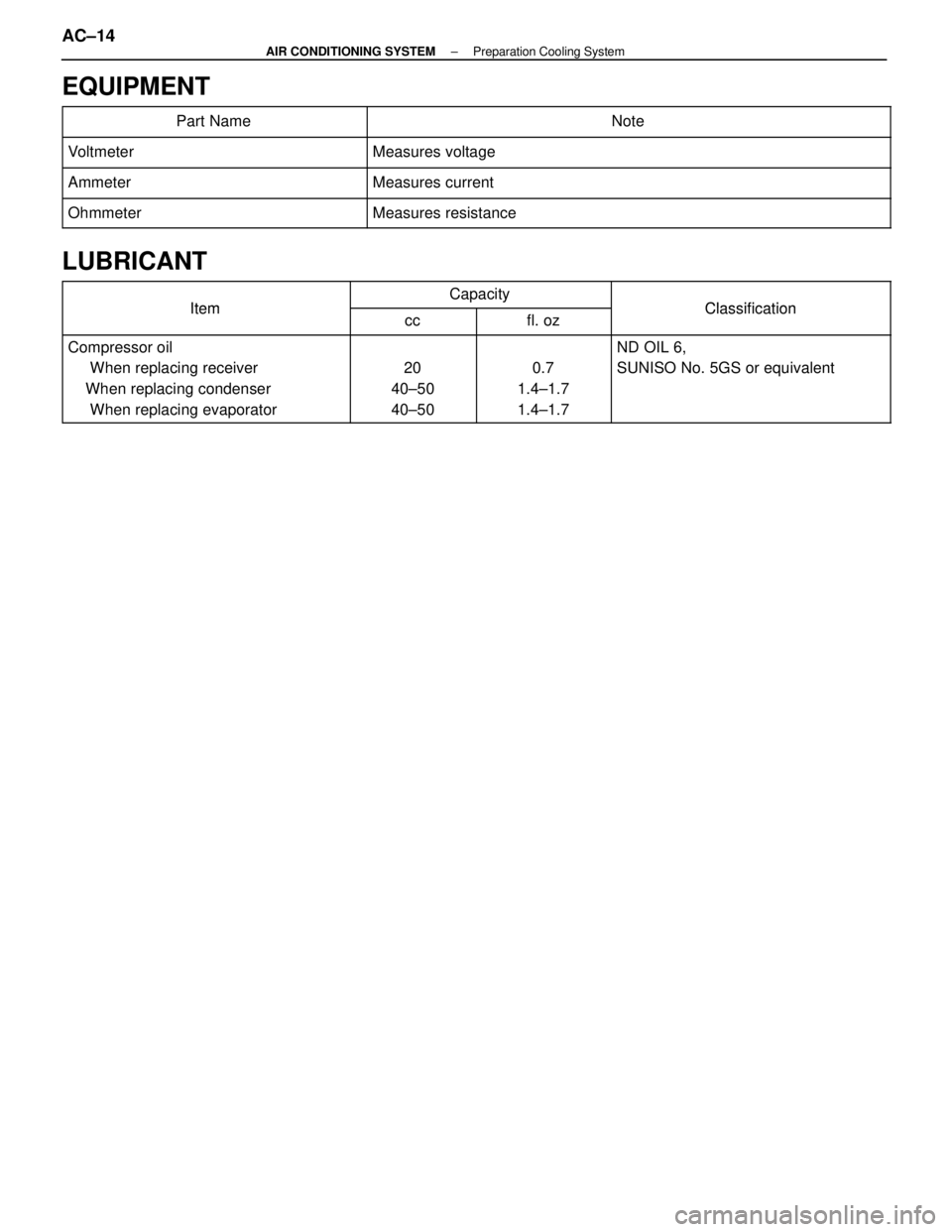
EQUIPMENT
�������������� ��������������Part Name������������������\
����� ������������������\
�����Note
�������������� �
�������������
��������������Voltmeter������������������\
����� �
������������������\
����
������������������\
�����Measures voltage�������������� �
�������������
��������������Ammeter
������������������\
����� �
������������������\
����
������������������\
�����Measures current
�������������� ��������������Ohmmeter������������������\
����� ������������������\
�����Measures resistance
LUBRICANT
ItemCapacityClassificationItemccfl. ozClassification
Compressor oil
When replacing receiver
When replacing condenser
When replacing evaporator
20
40±50
40±500.7
1.4±1.7
1.4±1.7
ND OIL 6,
SUNISO No. 5GS or equivalent
AC±14±
AIR CONDITIONING SYSTEM Preparation Cooling System
WhereEverybodyKnowsYourName
Page 87 of 4087

Diag. Code 13Evaporator Temperature Sensor Circuit
CIRCUIT DESCRIPTION
This sensor detects the temperature inside the cooling unit and sends the ap\
propriate signals to the air
conditioner control assembly.
Code No.Diag. Code Detecting ConditionTrouble area
13
Open or short in evaporator temperature sensor
circuit.�Evaporator temperature sensor.
� Harness or connector between evaporator
temperature sensor and A/C control
assembly.
� A/C control assembly.
DIAGNOSTIC CHART
Check voltage between terminals TE
and SG of air conditioner control as-
sembly
Check evaporator temperature sensor.
Check harness and connector between air
conditioner control assembly and evapora-
tor temperature sensor (See page IN-27).
Check and replace air conditioner control
assembly. 10Proceed to next circuit inspection
shown on matrix chart (See page
AC-36
). However, when Diag. code
13 is displayed, check and replace
air conditioner control assembly.
Replace evaporator temperature
sensor.
Repair or replace harness or
connector.
AC±48±
AIR CONDITIONING SYSTEM Troubleshooting
WhereEverybodyKnowsYourName
Page 104 of 4087
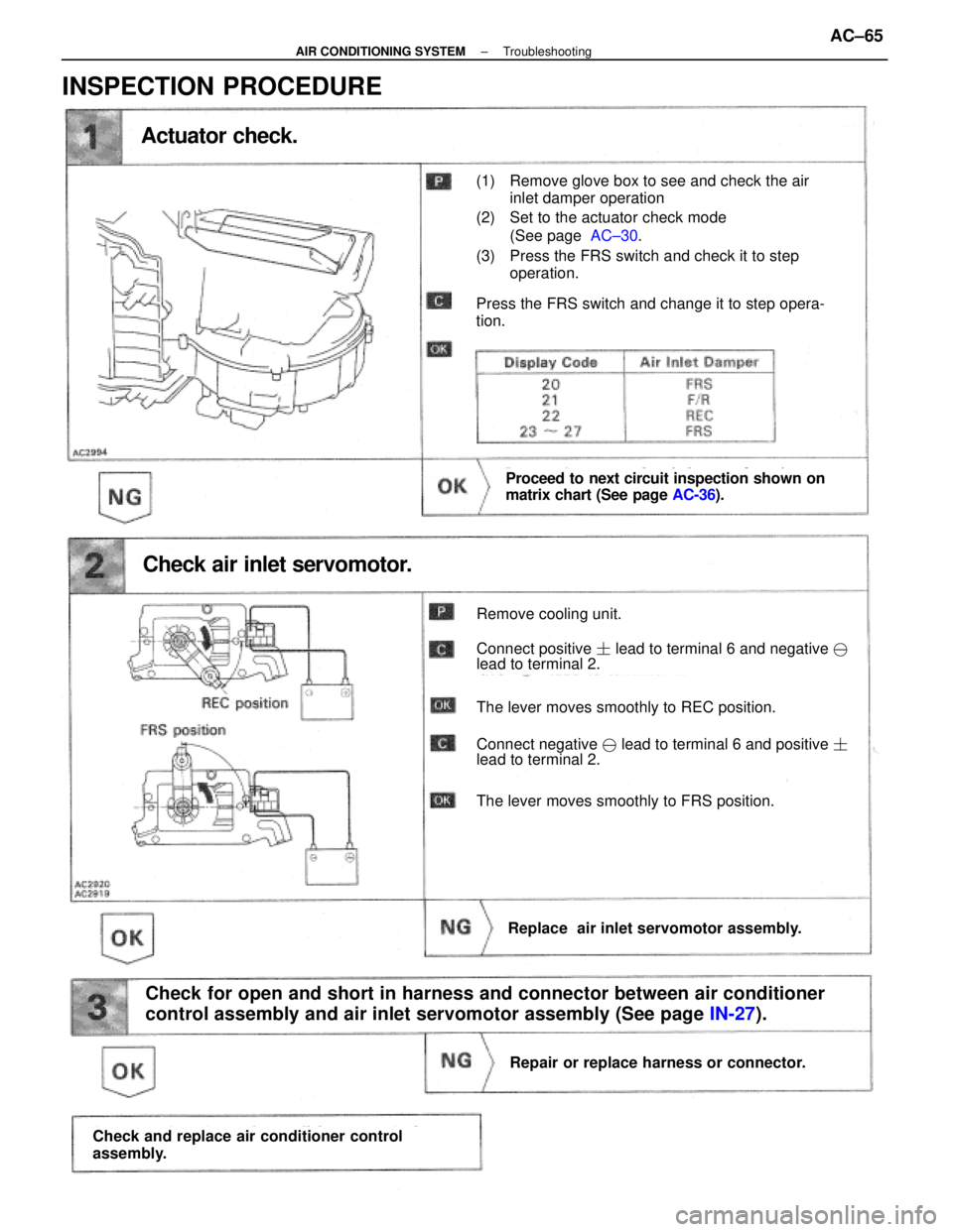
Actuator check.
Proceed to next circuit inspection shown on
matrix chart (See page AC-36).
Check air inlet servomotor.
Remove cooling unit.
Connect positive � lead to terminal 6 and negative �
lead to terminal 2.
The lever moves smoothly to REC position.
Connect negative � lead to terminal 6 and positive �
lead to terminal 2.
The lever moves smoothly to FRS position.
Replace air inlet servomotor assembly.
Check for open and short in harness and connector between air conditioner
control assembly and air inlet servomotor assembly (See page IN-27).
Repair or replace harness or connector.
Check and replace air conditioner control
assembly.
(1) Remove glove box to see and check the air
inlet damper operation
(2) Set to the actuator check mode (See page AC±30.
(3) Press the FRS switch and check it to step operation.
Press the FRS switch and change it to step opera-
tion.
INSPECTION PROCEDURE
±
AIR CONDITIONING SYSTEM TroubleshootingAC±65
WhereEverybodyKnowsYourName
Page 118 of 4087
Check power transistor.
(1) Remove cooling unit (See page BO-107).
(2) Disconnect power transistor connector.
(1) Check test bulb lights up when battery and
resistor are connected to power transistor
connector as left illustration shows.
(2) Measure resistance between terminal 2 and 3
(1) The bulb lights up.
(2)Resistance: 2.0± 2.4 ��k �
Replace power transistor.
Check for open and short in harness and connector between air
conditioner control assembly and power transistor (See page IN-27).
Repair or replace harness or connector.
Proceed to next circuit inspection shown on matrix
chart (See page AC-36).
INSPECTION PROCEDURE
±
AIR CONDITIONING SYSTEM TroubleshootingAC±79
WhereEverybodyKnowsYourName
Page 128 of 4087

������������������\
������������������\
�
������������������\
�����������������
������������������\
������������������\
Water Valve VSV Circuit
CIRCUIT DESCRIPTION
If the target air mix damper position is on the hot side beyond a predeter\
mined level, the A/C control
assembly turns ON Tr inside the A/C control assembly.
This turns the water valve VSV ON so that engine coolant flows to the he\
ater core.
If the target air mix damper position is on the cool side beyond a prede\
termined level, the A/C control
assembly OFF Tr inside the A/C control assembly.
This turns OFF the VSV and stops circulation of engine coolant to the he\
ater core, thus increasing the
cooling performance.
DIAGNOSTIC CHART
Check voltage between terminal WV of A/C
control assembly connector and body
ground .
Check water valve VSV.
Check for open and short in harness
and connector between VSV and A/C
control assembly .
Check and replace A/C control assembly.
Replace water valve VSV.
Repair or replace harness or
connector.
Proceed to next circuit inspection
shown on matrix chart
(See page
AC-36).
WIRING DIAGRAM
AC±90±
AIR CONDITIONING SYSTEM Troubleshooting
WhereEverybodyKnowsYourName
Page 137 of 4087
ConditionProbable cause Remedy
LO: 1.5 ± 2.0(21 ±28, 147 ±196)
HI: 14.5 ± 15.0(206 ±213, 1422 ±1471)
Normal coolingNormally functioning
system
During operati")
No.Gauge reading kPa (kgf/cm2, psi)ConditionProbable cause Remedy
LO: 1.5 ± 2.0(21 ±28, 147 ±196)
HI: 14.5 ± 15.0(206 ±213, 1422 ±1471)
Normal coolingNormally functioning
system
During operation, pressure at low
pressure side sometimes becomes a
vacuum and sometimes normal.Periodically cools
and then fails to
cool.Moisture present in
refrigeration system.(1). Replace receiver
(2). Remove moisturein system through
repeatedly
evacuating air
Inspection of Refrigeration System with Manifold Gauge Set
This is a method in which the trouble is located by using a manifold gauge s\
et. (See ºInstallation of Manifold
Gauge Setº on page AC±15) Read the manifold gauge pressure when the following conditions are es\
tablished:
(a) Temperature at the air inlet with the switch set at RECIRC is 30±35 °C (86±95 °F).
(b) Engine running at 2,000 rpm.
(c) Blower fan speed control switch set at high speed.
(d) Temperature control switch set at max. cool side.
HINT: It should be noted that the gauge indications may vary slightly due to\
ambient temperature conditions.
NOTICE:
w Always recover refrigerant before removing the parts in the refrigerant \
line and evacuating air.
w Evacuate air and charge proper amount of purified refrigerant after installing th\
e parts in the
refrigerant line.
AC±100
±
AIR CONDITIONING SYSTEM Troubleshooting
WhereEverybodyKnowsYourName
 Remove cooling unit (See page BO-107).
(2) Disconnect power transistor connector.
(1) Check test bulb lights up when battery and
resistor are connected to power transist")