Page 9 of 4087

12. Observe the following precautions to avoid damage to theparts:
(a) Do not open the cover or case of the ECU unless
absolutely necessary (If the IC terminals are touched, the
IC may be destroyed by static electricity.).
(b) To pull apart electrical connectors, pull on the connectoritself, not the wires (See page BE±2).
(c) Be careful not to drop electrical components, such as sensors or relays. It they are dropped on a hard floor,
they should be replaced and not reused.
(d) When checking continuity at the wire connector, insert the tester probe carefully to prevent terminals from
bending.
(e) To disconnect vacuum hoses, pull on the end, not the middle of the hose.
(f) When steam cleaning an engine, protect the distributor,
coil and air filter from water.
(g) Ne ve r use an imp a ct wre n ch to re mo ve or in sta ll temperature switches or temperature sensors.
(h) When using a vacuum gauge, never force the hose onto
a connector that is too large. Use a step±down adapter
instead. Once the hose has been stretched, it may leak.
13. Tag hoses before disconnecting them: (a) When disconnecting vacuum hoses, use tags to identify
how they should be reconnected.
(b) After completing a job, double check that the vacuum hoses are properly connected. A label under the hood
shows the proper layout.
14. Installation of wheels The wheel assemblies are of the uni±directional type and
must be rotated only between the front and rear as illustrated.
Wheels are marked with turning direction indicators.
When installing the wheels, check the marks carefully and
install the wheel correctly.
15. Bleeding of traction control system When repairing the brake master cylinder or TRAC system,
bleed the air out of the TRAC system (See page BR±7).
CAUTION: Since the fluid is under high pressure, it could
spray out with great force, so be careful.
IN±6
±
INTRODUCTION General Repair Instructions
WhereEverybodyKnowsYourName
Page 129 of 4087

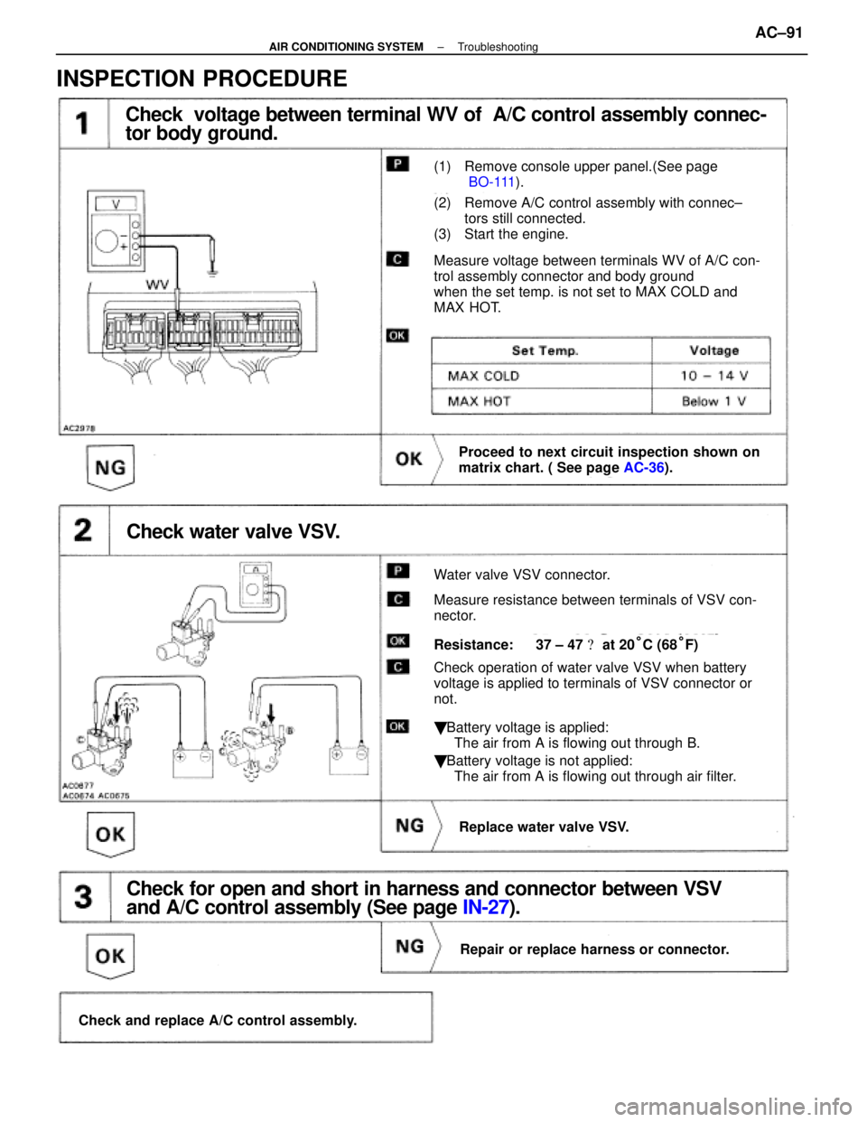
Check voltage between terminal WV of A/C control assembly connec-
tor body ground.
(1) Remove console upper panel.(See page
BO-111).
(2) Remove A/C control assembly with connec±
tors still connected.
(3) Start the engine.
Measure voltage between terminals WV of A/C con-
trol assembly connector and body ground
when the set temp. is not set to MAX COLD and
MAX HOT.
Proceed to next circuit inspection shown on
matrix chart. ( See page AC-36).
Check water valve VSV.
Water valve VSV connector.
Measure resistance between terminals of VSV con-
nector.
Resistance: 37 ± 47 � at 20°C (68°F)
Check operation of water valve VSV when battery
voltage is applied to terminals of VSV connector or
not.
� Battery voltage is applied:
The air from A is flowing out through B.
� Battery voltage is not applied:
The air from A is flowing out through air filter.
Replace water valve VSV.
Check for open and short in harness and connector between VSV
and A/C control assembly (See page IN-27).
Repair or replace harness or connector.
Check and replace A/C control assembly.
INSPECTION PROCEDURE
±
AIR CONDITIONING SYSTEM TroubleshootingAC±91
WhereEverybodyKnowsYourName
Page 1296 of 4087

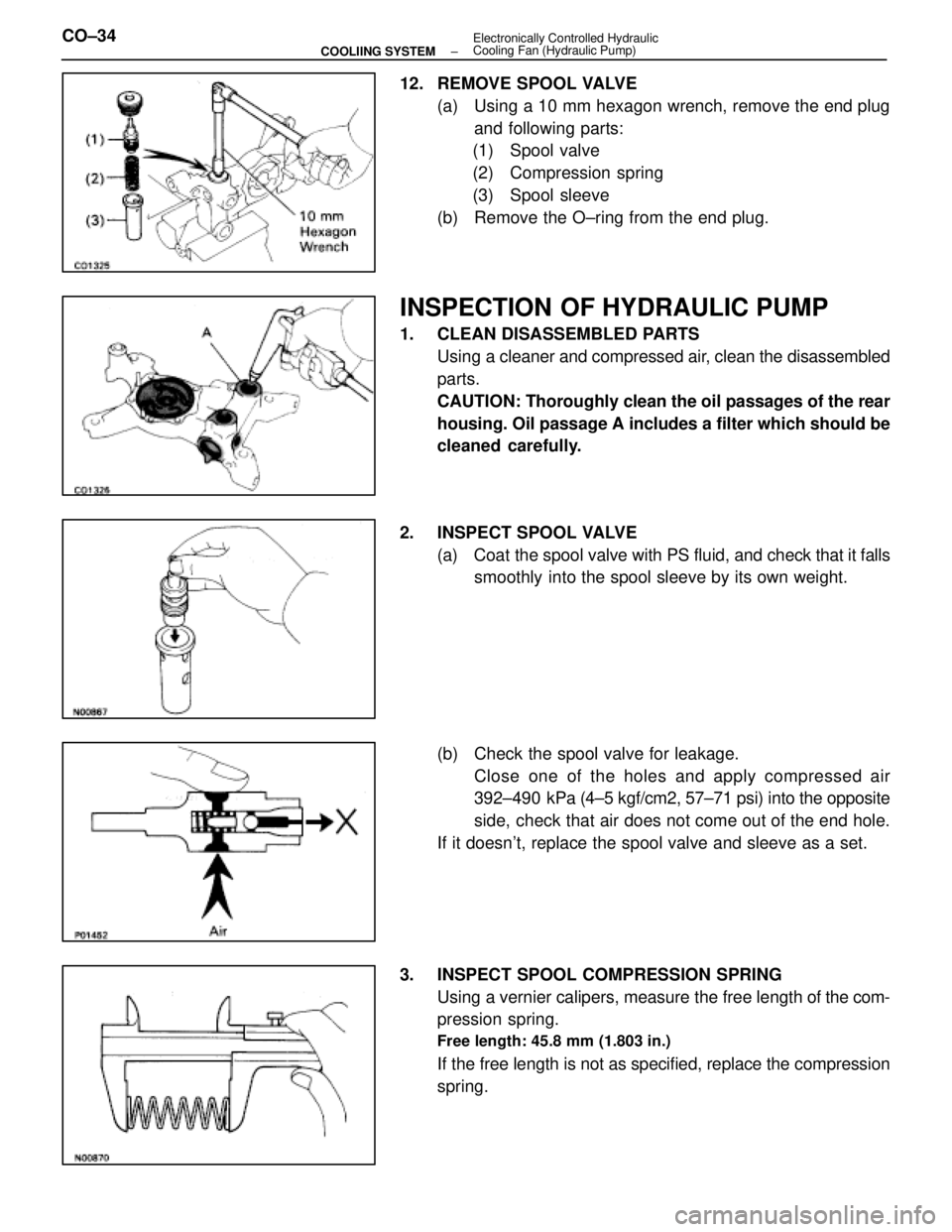
12. REMOVE SPOOL VALVE(a) Using a 10 mm hexagon wrench, remove the end plugand following parts:
(1) Spool valve
(2) Compression spring
(3) Spool sleeve
(b) Remove the O±ring from the end plug.
INSPECTION OF HYDRAULIC PUMP
1. CLEAN DISASSEMBLED PARTS Using a cleaner and compressed air, clean the disassembled
parts.
CAUTION: Thoroughly clean the oil passages of the rear
housing. Oil passage A includes a filter which should be
cleaned carefully.
2. INSPECT SPOOL VALVE (a) Coat the spool valve with PS fluid, and check that it falls
smoothly into the spool sleeve by its own weight.
(b) Check the spool valve for leakage. Close one of the holes and apply compressed air
392±490 kPa (4±5 kgf/cm2, 57±71 psi) into the opposite
side, check that air does not come out of the end hole.
If it doesn't, replace the spool valve and sleeve as a set.
3. INSPECT SPOOL COMPRESSION SPRING Using a vernier calipers, measure the free length of the com-
pression spring.
Free length: 45.8 mm (1.803 in.)
If the free length is not as specified, replace the compression
spring.
CO±34
±
COOLIING SYSTEM Electronically Controlled Hydraulic
Cooling Fan (Hydraulic Pump)
WhereEverybodyKnowsYourName
Page 1343 of 4087
3. VISUALLY INSPECT FUEL TANK CAPCheck if the cap and/or gasket are deformed or damaged.
If necessary, repair or replace the cap.
INSPECTION OF CHARCOAL CANISTER
1. REMOVE CHARCOAL CANISTER(a) Disconnect the following hoses:(1) Vacuum hose (from VSV) from charcoal canister
(2) EVAP hose from charcoal canister
(b) Disconnect the grommet on the check valve from the bracket, and remove the charcoal canister.
(c) Remove the check valve from the hose end on the charcoal canister.
2. VISUALLY INSPECT CHARCOAL CANISTER Look for cracks or damage.
3. CHECK FOR CLOGGED FILTER AND STUCK CHECK VA LV E
(a) Using low pressure compressed air, blow into port A and
check that air flows without resistance from the other
ports.
(b) Blow into port B and check that air does not flow from the
other ports.
If a problem is found, replace the charcoal canister.
±
EMISSION CONTROL SYSTEMS Fuel Evaporative Emission Control (EVAP) SystemEC±9
WhereEverybodyKnowsYourName
Page 1344 of 4087
4. CLEAN FILTER IN CANISTERClean the filter by blowing 294 kPa (3 kgf/cm2, 43 psi) of com-
pressed air into port A while holding port B closed.
NOTICE:
w Do not attempt to wash the canister.
w No activated carbon should come out.
5. REINSTALL CHARCOAL CANISTER
HINT: Install the check valve with black port facing the char-
coal canister side.
(a) Install the check valve to the hose end on the charcoalcanister.
(b) Install the charcoal canister.
(c) Install the grommet on the check valve to the bracket.
(d) Connect the following hoses: (1) Vacuum hose (from VSV) to charcoal canister
(2) EVAP hose to charcoal canister
COMPONENTS FOR REMOVAL AND INSTALLATION OF VSV
EC±10±
EMISSION CONTROL SYSTEMS Fuel Evaporative Emission Control (EVAP) System
WhereEverybodyKnowsYourName
Page 1350 of 4087
INSPECTION OF EGR SYSTEM
1. CHECK AND CLEAN FILTER IN EGR VACUUMMODULATOR
(a) Remove the cap and filter.
(b) Check the filter for contamination or damage.
(c) Using compressed air, clean the filter.
(d) Reinstall the filter and cap.
HINT: Install the filter with the coarser surface facing the at-
mospheric side (out ward).
2. INSPECT SYSTEM OPERATION (a) Connect the tachometer to terminal IG ± of the check(ºDIAGNOSISº) connector.
(b) Using SST connect the terminals TE1 and E1 of the check (ºDIAGNOSISº) connector.
SST 09843±18020
(c) Keep the engine at 3,500 rpm with the transmission in ºNº position.
(d) Remove the SST from the check connector.
SST 09843±18020
EC±12
±
EMISSION CONTROL SYSTEMS Exhaust Gas Recirculation (EGR) System
WhereEverybodyKnowsYourName
Page 1352 of 4087

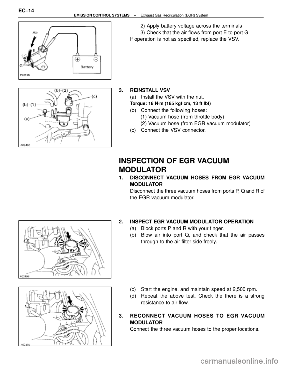
2) Apply battery voltage across the terminals
3) Check that the air flows from port E to port G
If operation is not as specified, replace the VSV.
3. REINSTALL VSV (a) Install the VSV with the nut.
Torque: 18 N Vm (185 kgf Vcm, 13 ft Vlbf)
(b) Connect the following hoses:
(1) Vacuum hose (from throttle body)
(2) Vacuum hose (from EGR vacuum modulator)
(c) Connect the VSV connector.
INSPECTION OF EGR VACUUM
MODULATOR
1. DISCONNECT VACUUM HOSES FROM EGR VACUUM MODULATOR
Disconnect the three vacuum hoses from ports P, Q and R of
the EGR vacuum modulator.
2. INSPECT EGR VACUUM MODULATOR OPERATION (a) Block ports P and R with your finger.
(b) Blow air into port Q, and check that the air passesthrough to the air filter side freely.
(c) Start the engine, and maintain speed at 2,500 rpm.
(d) Repeat the above test. Check the there is a strong resistance to air flow.
3. RECONNECT VACUUM HOSES TO EGR VACUUM MODULATOR
Connect the three vacuum hoses to the proper locations.
EC±14
±
EMISSION CONTROL SYSTEMS Exhaust Gas Recirculation (EGR) System
WhereEverybodyKnowsYourName
Page 1358 of 4087
INSPECTION OF EGR SYSTEM
(Exc. USA Spec.)
1. CHECK AND CLEAN FILTERS IN EGR VACUUMMODULATOR
(a) Remove the cap and filter.
(b) Check the filter for contamination or damage.
(c) Using compressed air, clean the filters.
(d) Reinstall the filter and cap.
HINT: Install the filter with the coarser surface facing the at-
mospheric side (outward).
2. INSPECT SYSTEM OPERATION (a) Using SST, connect terminals TE1 and E1 of the check
(ºDIAGNOSISº) connector.
SST 09843±18020
(b) Keep the engine at 3,500 rpm.
(c) Set the transmission shift lever to the ºNº position.
(d) Remove the SST from the check connector.
SST 09843±18020
(e) Check whether the engine rpm increases 100±300 rpm under the following conditions:
Coolant temp.
Below 53 5C (127 5F) No increase
Above 55 5C (131 5F) Increases
EC±18
±
EMISSION CONTROL SYSTEMS Exhaust Gas Recirculation (EGR) System
WhereEverybodyKnowsYourName