Page 1702 of 4087
 Check oxygen sensor operation.(See page FI±113)
(b) See the tabl")
Troubleshooting
If the HC/CO concentration does not comply with regulations,
perform troubleshooting in the order given below.
(a) Check oxygen sensor operation.(See page FI±113)
(b) See the table below for possible cause, and then inspect
and correct the applicable causes if necessary.
����� �
����
�����HC����� �
����
�����CO���������� �
���������
����������Symptoms������������������\
� �
������������������
������������������\
�Cause
����� �����High����� �����Normal���������� ����������Rough idle������������������\
� ������������������\
�1. Faulty ignitions:
����� ���������� ��������������� ����������������������������\
� ������������������\
��Incorrect timing
����� ���������� ��������������� ����������������������������\
� ������������������\
��Fouled, shorted or improperly gapped plugs
����� ���������� ��������������� ����������������������������\
� ������������������\
��Open or crossed high±tension cords
Ckddiib��������������������������������������\
��Cracked distributor cap
Ill����� ���������� ��������������� ����������������������������\
� ������������������\
�2. Incorrect valve clearance
3 L k EGR l����� ���������� ��������������� ����������������������������\
� ������������������\
�3. Leaky EGR valve
4L k i k d h l����� ���������� ��������������� ����������������������������\
� ������������������\
�4. Leaky intake and exhaust valves
L k li d����� ���������� ��������������� ����������������������������\
� ������������������\
�5. Leaky cylinders
����� �����High����� �����Low���������� ����������Rough idle������������������\
� ������������������\
�1. Vacuum leaks:
����� ���������� ��������������� ����������(Fluctuating HC reading)������������������\
� ������������������\
��PCV hoses
����� ���������� ��������������� ����������������������������\
� ������������������\
��EGR valve
����� ���������� ��������������� ����������������������������\
� ������������������\
��Intake manifold
Ai i k h b����� ���������� ��������������� ����������������������������\
� ������������������\
��Air intake chamber
Th l b d����� ���������� ��������������� ����������������������������\
� ������������������\
��Throttle body
ISC l��������������������������������������\
��ISC valve
Bkb li����� ���������� ��������������� ����������������������������\
� ������������������\
��Brake booster line
2L i i ifi����� ���������� ��������������� ����������������������������\
� ������������������\
�2. Lean mixture causing misfire
����� �����High����� �����High���������� ����������Rough idle������������������\
� ������������������\
�1. Clogged air filter����� �����g����� �����g���������� ����������g
(Black smoke from exhaust)������������������\
� ������������������\
�gg
2. Faulty EFI systems:����� ���������� ��������������� ����������()������������������\
� ������������������\
�yy
�Faulty pressure regulator
����� ���������� ��������������� ����������������������������\
� ������������������\
�
yg
�Clogged fuel return line
����� ���������� ��������������� ����������������������������\
� ������������������\
�
gg
�Defective water temp. sensor
����� ���������� ��������������� ����������������������������\
� ������������������\
��Defective air temp. sensor
����� ���������� ��������������� ����������������������������\
� ������������������\
��Faulty ECU
����� ���������� ��������������� ����������������������������\
� ������������������\
�
y
�Faulty injectors
��������������������������������������\
�
yj
�Faulty cold start injector����� ���������� ��������������� ����������������������������\
� ������������������\
�yj
�Faulty throttle position sensor����� ���������� ��������������� ����������������������������\
� ������������������\
��Faulty air flow meter
±
ENGINE MECHANICAL Idle and/or 2,500 rpm HC/CO
Concentration Check MethodEM±29
WhereEverybodyKnowsYourName
Page 1709 of 4087
7. REMOVE INTAKE AIR CONNECTOR(a) Disconnect the following hoses:(1) Air hose from ISC valve
(2) Air hose (from PS air control valve) from intake air connector
(b) Remove the bolt holding the intake air connector to the cylinder head cover.
(c) Loosen the two hose clamps.
(d) Disconnect the intake air connector from the throttle
body and air cleaner hose, and remove the throttle body.
8. REMOVE LH IGNITION COIL (a) Disconnect the following connectors and cord:(1) Ignition coil connector
(2) Noise filter connector
(3) High±tension cord
(b) Remove the two bolts and ignition coil.
9. REMOVE UPPER HIGH±TENSION CORD COVER (a) Remove the two mounting bolts.
(b) Disconnect the front side claw groove of the cord coverfrom the claw of the lower cover, and remove the cord
cover.
EM±36
±
ENGINE MECHANICAL Timing Belt
WhereEverybodyKnowsYourName
Page 1729 of 4087
35. INSTALL LH IGNITION COIL(a) Install the ignition coil with the two bolts.
(b) Connect the following connectors and cord:(1) Ignition coil connector
(2) Noise filter connector
(3) High±tension cord
36. INSTALL INTAKE AIR CONNECTOR (a) Connect the end portions of the intake air connector tothe throttle body and air cleaner hose.
(b) Tighten the two hose clamps.
(c) Install the bolt holding the intake air connector to the cylinder head cover.
(d) Connect the following hoses: (1) Air hose to ISC valve
(2) Air hose (from PS air control valve) to intake air connector
EM±56
±
ENGINE MECHANICAL Timing Belt
WhereEverybodyKnowsYourName
Page 1831 of 4087
PREPARATION FOR DISASSEMBLY
(See Components on pages EM±74 and 75)1. (M/T) REMOVE FLYWHEEL
2. (A/T) REMOVE DRIVE PLATE
Remove the eight bolts, two spacers and drive plate.
3. INSTALL ENGINE TO ENGINE STAND FOR DISASSEMBLY
4. REMOVE GENERATOR
5. REMOVE THROTTLE BODY WITH INTAKE AIR CONNECTOR (See pages EM±10 to 11)
6. REMOVE TIMING BELT AND PULLEYS (See pages EM±24 to 26)
7. REMOVE WATER PUMP AND BY±PASS HOSE
8. REMOVE FUEL PRESSURE PULSATION DAMPER
9. REMOVE CYLINDER HEAD (See pages EM±36 to 40)
10. REMOVE FUEL PIPE SUPPORT
11. REMOVE OIL PRESSURE SWITCH AND KNOCK SENSORS
SST 09816±30010
12. REMOVE LH ENGINE MOUNTING BRACKET
13. REMOVE RH ENGINE MOUNTING BRACKET
14. REMOVE OIL FILTER BRACKET (a) Remove the union bolt and oil filter bracket.
(b) Remove the gasket from the union bolt.
(c) Remove the O±ring from the oil filter bracket.
15. REMOVE OIL PUMP (See page LU±10)
EM±76
±
ENGINE MECHANICAL Cylinder Block
WhereEverybodyKnowsYourName
Page 1892 of 4087
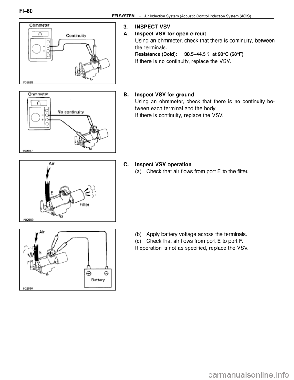
3. INSPECT VSV
A. Inspect VSV for open circuitUsing an ohmmeter, check that there is continuity, between
the terminals.
Resistance (Cold): 38.5±44.5 � at 20 5C (68 5F)
If there is no continuity, replace the VSV.
B. Inspect VSV for ground Using an ohmmeter, check that there is no continuity be-
tween each terminal and the body.
If there is continuity, replace the VSV.
C. Inspect VSV operation (a) Check that air flows from port E to the filter.
(b) Apply battery voltage across the terminals.
(c) Check that air flows from port E to port F.
If operation is not as specified, replace the VSV.
FI±60
±
EFI SYSTEM
Air Induction System (Acoustic Control Induction System (ACIS)
WhereEverybodyKnowsYourName
Page 1899 of 4087
PRECAUTIONS
1. Always use new gaskets when replacing the fuel tank orcomponent part.
2. Apply the proper torque to all parts tightened.
INSPECTION OF FUEL LINES AND
CONNECTIONS
(a) Inspect the fuel lines and connections for cracks,
leakage or deformation.
(b) Inspect the fuel tank vapor vent system hoses and connections for looseness, kinks or damage.
(c) Inspect the fuel tank for deformation, cra cks, fuel
leakage or tank band looseness.
(d) Check the filter neck for damage or fuel leakage.
(e) Ho se an d tu b e c onnections are as shown in the
illustration.
If a problem is found, repair or replace the parts as necessary.
FI±62
EFI SYSTEM
± Fuel System (Fuel Tank and Lines)
WhereEverybodyKnowsYourName
Page 1906 of 4087
ON±VEHICLE INSPECTION
1. INSPECT THROTTLE BODY(a) Remove the throttle body cover.w Remove the mounting cap nut.
w Loosen the two bolts, and remove the throttle body
cover.
(b) Check that the throttle linkage moves smoothly.
(c) Check the vacuum at each port. w Start the engine.
w Check the vacuum with your finger.
Port nameAt idlingAt 3,000 rpm
PNo vacuumVacuum
*ENo vacuumVacuum
*RNo vacuumVacuum
* Exc. USA Spec.
(d) Reinstall the throttle body cover.
3. INSPECT AND ADJUST DASH POT (DP)
A. Warm up engine Allow the engine to warm up to normal operating tempera-
ture.
B. Check idle speed
Idle speed: 700 + 50 rpm
C. Remove cap, filter and separator from DP FI±67
EFI SYSTEM
± Air Induction System (Throttle Body)
WhereEverybodyKnowsYourName
Page 1907 of 4087
D. Check and adjust DP setting speed(a) Maintain the engine at 2,500 rpm.
(b) Plug the VTV hole with your finger.
(c) Release the throttle valve.
(d) Check that the DP is set.
DP setting speed: 1,500 rpm
(e) Adjust the DP setting speed by turning the DP adjusting
screw.
(f) Repeat steps from (a) to (c), and recheck the DP setting
speed.
E. Reinstall separator, filter and cap to DP HINT: Install the filter with the coarser surface facing the at-
mospheric side (outward).
F. Check VTV operation (a) Maintain the engine at 2,500 rpm.
(b) Release the throttle valve, and check that the enginereturns to idle in a few seconds.
FI±68
EFI SYSTEM
± Air Induction System (Throttle Body)
WhereEverybodyKnowsYourName
 Disconnect the following hoses:(1) Air hose from ISC valve
(2) Air hose (from PS air control valve) from intake air connector
(b) Remove the bolt holding the inta")
 Install the ignition coil with the two bolts.
(b) Connect the following connectors and cord:(1) Ignition coil connector
(2) Noise filter connector
(3) High±tension")
1. (M/T) REMOVE FLYWHEEL
2. (A/T) REMOVE DRIVE PLATE
Remove the eight bolts, two spacers and drive plate.
3. INSTALL ENGINE TO ENGI")
 Inspect the fue")
 Remove the throttle body cover.w Remove the mounting cap nut.
w Loosen the two bolts, and remove the throttle body
cover.
(b) Check that the thr")
 Maintain the engine at 2,500 rpm.
(b) Plug the VTV hole with your finger.
(c) Release the throttle valve.
(d) Check that the DP is set.
DP setting speed:")