Page 2442 of 4087
PRECAUTIONS
1. Always use new gaskets when replacing the fuel tank orcomponent part.
2. Apply the proper torque to all parts tightened.
INSPECTION OF FUEL LINES AND
CONNECTIONS
(a) Inspect the fuel lines and connections for cracks,
leakage or deformation.
(b) Inspect the fuel tank vapor vent system hoses and connections for looseness, kinks or damage.
(c) Inspect the fuel tank for deformation, cra cks, fuel
leakage or tank band looseness.
(d) Check the filter neck for damage or fuel leakage.
(e) Ho se an d tu b e c onnections are as shown in the
illustration.
If a problem is found, repair or replace the parts as necessary.
FI±62
EFI SYSTEM
± Fuel System (Fuel Tank and Lines)
WhereEverybodyKnowsYourName
Page 2447 of 4087
ON±VEHICLE INSPECTION
1. INSPECT THROTTLE BODY(a) Remove the throttle body cover.w Remove the mounting cap nut.
w Loosen the two bolts, and remove the throttle body
cover.
(b) Check that the throttle linkage moves smoothly.
(c) Check the vacuum at each port. w Start the engine.
w Check the vacuum with your finger.
Port nameAt idlingAt 3,000 rpm
PNo vacuumVacuum
*ENo vacuumVacuum
*RNo vacuumVacuum
* Exc. USA Spec.
(d) Reinstall the throttle body cover.
3. INSPECT AND ADJUST DASH POT (DP)
A. Warm up engine Allow the engine to warm up to normal operating tempera-
ture.
B. Check idle speed
Idle speed: 700 + 50 rpm
C. Remove cap, filter and separator from DP FI±67
EFI SYSTEM
± Air Induction System (Throttle Body)
WhereEverybodyKnowsYourName
Page 2448 of 4087
D. Check and adjust DP setting speed(a) Maintain the engine at 2,500 rpm.
(b) Plug the VTV hole with your finger.
(c) Release the throttle valve.
(d) Check that the DP is set.
DP setting speed: 1,500 rpm
(e) Adjust the DP setting speed by turning the DP adjusting
screw.
(f) Repeat steps from (a) to (c), and recheck the DP setting
speed.
E. Reinstall separator, filter and cap to DP HINT: Install the filter with the coarser surface facing the at-
mospheric side (outward).
F. Check VTV operation (a) Maintain the engine at 2,500 rpm.
(b) Release the throttle valve, and check that the enginereturns to idle in a few seconds.
FI±68
EFI SYSTEM
± Air Induction System (Throttle Body)
WhereEverybodyKnowsYourName
Page 2473 of 4087
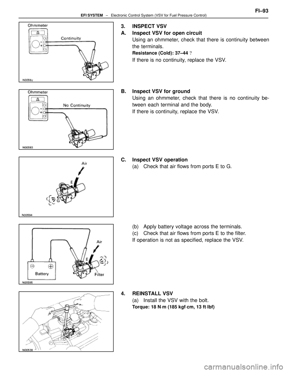
3. INSPECT VSV
A. Inspect VSV for open circuitUsing an ohmmeter, check that there is continuity between
the terminals.
Resistance (Cold): 37±44 �
If there is no continuity, replace the VSV.
B. Inspect VSV for ground Using an ohmmeter, check that there is no continuity be-
tween each terminal and the body.
If there is continuity, replace the VSV.
C. Inspect VSV operation (a) Check that air flows from ports E to G.
(b) Apply battery voltage across the terminals.
(c) Check that air flows from ports E to the filter.
If operation is not as specified, replace the VSV.
4. REINSTALL VSV (a) Install the VSV with the bolt.
Torque: 18 N Vm (185 kgf Vcm, 13 ft Vlbf)
FI±93EFI SYSTEM ± Electronic Control System (VSV for Fuel Pressure Control)
WhereEverybodyKnowsYourName
Page 2558 of 4087

A pressure feeding lubrication system has been adopted to supply oil to \
the moving parts of this engine. The
lubrication system consists of an oil pan, oil pump, oil filter and other external p\
arts which supply oil to the moving
parts in the engine block. The oil circuit is shown in the illustration at th\
e top of the previous page. Oil from the
oil pan is pumped up by the oil pump. After it passes through the oil fi\
lter, it is fed through the various oil holes
in the crankshaft and cylinder block. After passing through the cylinder b\
lock and performing its lubricating func-
tion, the oil is returned by gravity to the oil pan. A dipstick on the center\
left side of the cylinder block is provided
to check the oil level.
OIL PUMP The oil pump pumps up oil from the oil pan and sends it under pressure to t\
he various parts of the engine.
An oil strainer is mounted in front of the inlet to the oil pump. The oil \
pump itself is a trochoid type pump, inside
of which there is a drive rotor and a driven rotor. When the drive rotor rotates, the driven rotor rotates in the same
direction, and since the axis of the driven rotor shaft is different from the center of the driven rotor, the space
between the two rotors is changed as they rotate. Oil is drawn in when the space\
is wide and is discharged when
the space in narrow.
OIL PRESSURE REGULATOR At high engine speeds, the engine oil supplied by the oil pump exceeds the\
capacity of the engine to utilize
it. For that reason, the oil pressure regulator works to prevent an over\
supply of oil. During normal oil supply, a
coil spring and valve keep the bypass closed, but when too much oil is being \
fed, the pressure become extremely
high, overpowering the force of the spring and opening the valves. This allow\
s the excess oil to flow through
the valve and return to the oil pump inlet.
OIL FILTER The oil filter is a full flow type filter with a built±in paper filter e\
lement. Particles of metal from wear, airborne
dirt, carbon and other impurities can get into the oil during use and co\
uld cause accelerated wear or seizing if
allowed to circulate through the engine. The oil filter, integrated into the oil line, removes these impurities as the
oil passes through it. The filter is mounted outside the engine to simplify\
replacement of the filter element. A relief
valve is also included ahead of the filter element to relieve the high oil pr\
essure in case the filter element be-
comes clogged with impurities. The relief valve opens when the oil pressure o\
verpowers the force of the spring.
Oil passing through the relief valve by±passes the oil filter and flo\
ws directly into the main oil hole in the engine.
±
LUBRICATION SYSTEM PrecautionsLU±3
WhereEverybodyKnowsYourName
Page 2635 of 4087

YESNO
NOYES
YES
NO
OKNG
BASIC INSPECTION
When the normal code is displayed in the diagnostic code check, troubleshoot\
ing should be performed in the
order for all possible circuits to be considered as the causes of the pr\
oblems.
In many cases, by carrying out the basic engine check shown in the follo\
wing flow chart, the location causing
the problem can be found quickly and ef ficiently. Therefore, use of this check is essential in engine troubleshoot-
ing.
1Is battery voltage 11 V or more when engine is stopped?
Charge or replace battery.
2Is engine cracnked?
Proceed to matrix to matrix chart of problem
symptoms on page TR±35.
3Does engine start?
Go to step [7]
4Check air filter
C
Hint
PRemove air filter
Visially check that the air cleaner element is not exces-
sively damaged or oily.
If necessary, clean element with compressed air. First
blow from inside thoroughly, then blow off outside of ele-
ment.
Repair or replace
Go to Step [5].
TR±24±
ENGINE TROUBLESHOOTING Basic Inspection
WhereEverybodyKnowsYourName
Page 2820 of 4087
 Using a 10 mm hexagon wrench, remove the end plugand following parts:
(1) Spool valve
(2) Compression spring
(3) Spool sleeve
(b) Remove the O±ring from the end plug.
IN")
12. REMOVE SPOOL VALVE(a) Using a 10 mm hexagon wrench, remove the end plugand following parts:
(1) Spool valve
(2) Compression spring
(3) Spool sleeve
(b) Remove the O±ring from the end plug.
INSPECTION OF HYDRAULIC PUMP
1. CLEAN DISASSEMBLED PARTS Using a cleaner and compressed air, clean the disassembled
parts.
CAUTION: Thoroughly clean the oil passages of the rear
housing. Oil passage A includes a filter which should be
cleaned carefully.
2. INSPECT SPOOL VALVE (a) Coat the spool valve with PS fluid, and check that it falls
smoothly into the spool sleeve by its own weight.
(b) Check the spool valve for leakage. Close one of the holes and apply compressed air
392±490 kPa (4±5 kgf/cm2, 57±71 psi) into the opposite
side, check that air does not come out of the end hole.
If it doesn't, replace the spool valve and sleeve as a set.
3. INSPECT SPOOL COMPRESSION SPRING Using a vernier calipers, measure the free length of the com-
pression spring.
Free length: 45.8 mm (1.803 in.)
If the free length is not as specified, replace the compression
spring.
CO±34
±
COOLIING SYSTEM Electronically Controlled Hydraulic
Cooling Fan (Hydraulic Pump)
WhereEverybodyKnowsYourName
Page 2860 of 4087
3. VISUALLY INSPECT FUEL TANK CAPCheck if the cap and/or gasket are deformed or damaged.
If necessary, repair or replace the cap.
INSPECTION OF CHARCOAL CANISTER
1. REMOVE CHARCOAL CANISTER(a) Disconnect the following hoses:(1) Vacuum hose (from VSV) from charcoal canister
(2) EVAP hose from charcoal canister
(b) Disconnect the grommet on the check valve from the bracket, and remove the charcoal canister.
(c) Remove the check valve from the hose end on the charcoal canister.
2. VISUALLY INSPECT CHARCOAL CANISTER Look for cracks or damage.
3. CHECK FOR CLOGGED FILTER AND STUCK CHECK VA LV E
(a) Using low pressure compressed air, blow into port A and
check that air flows without resistance from the other
ports.
(b) Blow into port B and check that air does not flow from the
other ports.
If a problem is found, replace the charcoal canister.
±
EMISSION CONTROL SYSTEMS Fuel Evaporative Emission Control (EVAP) SystemEC±9
WhereEverybodyKnowsYourName
 Inspect the fue")
 Remove the throttle body cover.w Remove the mounting cap nut.
w Loosen the two bolts, and remove the throttle body
cover.
(b) Check that the thr")
 Maintain the engine at 2,500 rpm.
(b) Plug the VTV hole with your finger.
(c) Release the throttle valve.
(d) Check that the DP is set.
DP setting speed:")
 Dis")