Page 2861 of 4087
4. CLEAN FILTER IN CANISTERClean the filter by blowing 294 kPa (3 kgf/cm2, 43 psi) of com-
pressed air into port A while holding port B closed.
NOTICE:
w Do not attempt to wash the canister.
w No activated carbon should come out.
5. REINSTALL CHARCOAL CANISTER
HINT: Install the check valve with black port facing the char-
coal canister side.
(a) Install the check valve to the hose end on the charcoalcanister.
(b) Install the charcoal canister.
(c) Install the grommet on the check valve to the bracket.
(d) Connect the following hoses: (1) Vacuum hose (from VSV) to charcoal canister
(2) EVAP hose to charcoal canister
COMPONENTS FOR REMOVAL AND INSTALLATION OF VSV
EC±10±
EMISSION CONTROL SYSTEMS Fuel Evaporative Emission Control (EVAP) System
WhereEverybodyKnowsYourName
Page 2869 of 4087
INSPECTION OF EGR SYSTEM
(Exc. USA Spec.)
1. CHECK AND CLEAN FILTERS IN EGR VACUUMMODULATOR
(a) Remove the cap and filter.
(b) Check the filter for contamination or damage.
(c) Using compressed air, clean the filters.
(d) Reinstall the filter and cap.
HINT: Install the filter with the coarser surface facing the at-
mospheric side (outward).
2. INSPECT SYSTEM OPERATION (a) Using SST, connect terminals TE1 and E1 of the check
(ºDIAGNOSISº) connector.
SST 09843±18020
(b) Keep the engine at 3,500 rpm.
(c) Set the transmission shift lever to the ºNº position.
(d) Remove the SST from the check connector.
SST 09843±18020
(e) Check whether the engine rpm increases 100±300 rpm under the following conditions:
Coolant temp.
Below 53 5C (127 5F) No increase
Above 55 5C (131 5F) Increases
EC±18
±
EMISSION CONTROL SYSTEMS Exhaust Gas Recirculation (EGR) System
WhereEverybodyKnowsYourName
Page 2871 of 4087

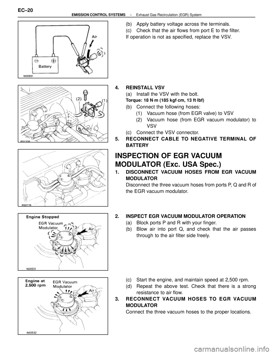
(b) Apply battery voltage across the terminals.
(c) Check that the air flows from port E to the filter.
If operation is not as specified, replace the VSV.
4. REINSTALL VSV (a) Install the VSV with the bolt.
Torque: 18 N Vm (185 kgf Vcm, 13 ft Vlbf)
(b) Connect the following hoses:
(1) Vacuum hose (from EGR valve) to VSV
(2) Vacuum hose (from EGR vacuum modulator) to VSV
(c) Connect the VSV connector.
5. RECONNECT CABLE TO NEGATIVE TERMINAL OF BATTERY
INSPECTION OF EGR VACUUM
MODULATOR (Exc. USA Spec.)
1. DISCONNECT VACUUM HOSES FROM EGR VACUUMMODULATOR
Disconnect the three vacuum hoses from ports P, Q and R of
the EGR vacuum modulator.
2. INSPECT EGR VACUUM MODULATOR OPERATION (a) Block ports P and R with your finger.
(b) Blow air into port Q, and check that the air passesthrough to the air filter side freely.
(c) Start the engine, and maintain speed at 2,500 rpm.
(d) Repeat the above test. Check that there is a strong resistance to air flow.
3. RECONNECT VACUUM HOSES TO EGR VACUUM MODULATOR
Connect the three vacuum hoses to the proper locations.
EC±20
±
EMISSION CONTROL SYSTEMS Exhaust Gas Recirculation (EGR) System
WhereEverybodyKnowsYourName
Page 3397 of 4087

YESNO
NOYES
YES
NO
OKNG
BASIC INSPECTION
When the normal code is displayed in the diagnostic code check, troubleshoot\
ing should be performed in the
order for all possible circuits to be considered as the causes of the pr\
oblems.
In many cases, by carrying out the basic engine check shown in the follo\
wing flow chart, the location causing
the problem can be found quickly and ef ficiently. Therefore, use of this check is essential in engine troubleshoot-
ing.
1Is battery voltage 11 V or more when engine is stopped?
Charge or replace battery.
2Is engine cracnked?
Proceed to matrix to matrix chart of problem
symptoms on page TR±35.
3Does engine start?
Go to step [7]
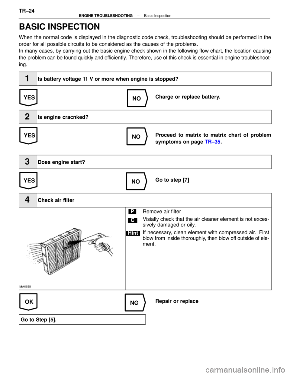
4Check air filter
C
Hint
PRemove air filter
Visially check that the air cleaner element is not exces-
sively damaged or oily.
If necessary, clean element with compressed air. First
blow from inside thoroughly, then blow off outside of ele-
ment.
Repair or replace
Go to Step [5].
TR±24±
ENGINE TROUBLESHOOTING Basic Inspection
WhereEverybodyKnowsYourName
Page 3538 of 4087
OKNG
NGOK
OKNG
INSPECTION PROCEDURE
1Check fuel pump operation.
C
OK
P1. Turn ignition switch ON.
2. Using SST, connect terminals +B and FP of checkconnector.
SST 09843±18020
Check that there is pressure in the hose from the fuel
filter.
Fuel pressure can be felt.
Go to step �.
2Check for open and short in harness and connector between terminals +B e�+B, FP � FP of
the check connector and fuel pump ECU (See page IN±27).
Go to step �.
Repair or replace harness or connector.
3Check voltage of terminal +B of check connector.
C
OK
PTurn ignition switch ON.
Measure voltage between terminal +B of check connec-
tor and body ground.
Voltage: 10 ± 14 V
Check for ECU power source circuit (See page TR±120),
and check for open in harness and connector between
terminal +B of check connector and main relay.
TR±112
±
ENGINE TROUBLESHOOTING Circuit Inspection
WhereEverybodyKnowsYourName
Page 3609 of 4087

YESNO
NOYES
YES
NO
OKNG
BASIC INSPECTION
When the normal code is displayed in the diagnostic code check, troubleshoot\
ing should be performed in the
order for all possible circuits to be considered as the causes of the pr\
oblems.
In many cases, by carrying out the basic engine check shown in the follo\
wing flow chart, the location causing
the problem can be found quickly and ef ficiently. Therefore, use of this check is essential in engine troubleshoot-
ing.
1Is battery voltage 11 V or more when engine is stopped?
Charge or replace battery.
2Is engine cracnked?
Proceed to matrix to matrix chart of problem
symptoms on page TR±35.
3Does engine start?
Go to step [7]
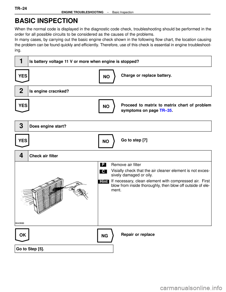
4Check air filter
C
Hint
PRemove air filter
Visially check that the air cleaner element is not exces-
sively damaged or oily.
If necessary, clean element with compressed air. First
blow from inside thoroughly, then blow off outside of ele-
ment.
Repair or replace
Go to Step [5].
TR±24±
ENGINE TROUBLESHOOTING Basic Inspection
WhereEverybodyKnowsYourName
Page 3750 of 4087
OKNG
NGOK
OKNG
INSPECTION PROCEDURE
1Check fuel pump operation.
C
OK
P1. Turn ignition switch ON.
2. Using SST, connect terminals +B and FP of checkconnector.
SST 09843±18020
Check that there is pressure in the hose from the fuel
filter.
Fuel pressure can be felt.
Go to step �.
2Check for open and short in harness and connector between terminals +B e�+B, FP � FP of
the check connector and fuel pump ECU (See page IN±27).
Go to step �.
Repair or replace harness or connector.
3Check voltage of terminal +B of check connector.
C
OK
PTurn ignition switch ON.
Measure voltage between terminal +B of check connec-
tor and body ground.
Voltage: 10 ± 14 V
Check for ECU power source circuit (See page TR±120),
and check for open in harness and connector between
terminal +B of check connector and main relay.
TR±112
±
ENGINE TROUBLESHOOTING Circuit Inspection
WhereEverybodyKnowsYourName
Page 3777 of 4087

AIR CONDITIONING EVAPORATOR ODOR ± AC001±97 September 12, 1997
General1. Preparation of freshener solution:
Procedure (a) Invert freshener container and shake vigorously for 30 seconds.
(b) Mix 3.4 fl. oz. of freshener (1 container) with 30 fl. oz. to make 1 q\
t. of solution.
2. Drying the evaporator: � Dry the evaporator for 10 minutes with the following settings:
A/C: Off
. . . . . . . . . . .
Air Outlet: Foot
. . . . . .
Mode: Recirc.
. . . . . . . . . .
Blower: High
. . . . . . . .
Te m p : Max Warm
. . . . . . . . . .
3. Evaporator Treatment Preparation: (a) Ensure availability of 30±45 psi compressed air to be used with spray\
gun for application of freshener.
(b) Place a tray under the evaporator housing drain hose to collect used cle\
aning solution.
(c) Place shop cloth under the evaporator housing in the vehicle to prevent \
cleaning solution from dripping onto the floor mat.
4. Vehicle Preparation: See specific model section.
5. Evaporator treatment: (a) Set HVAC mode as follows: A/C: Off
. . . . . . . . . . .
Air Outlet: Face
. . . . . .
Mode: Fresh
. . . . . . . . . .
Blower: High
. . . . . . . .
Te m p : Max Warm
. . . . . . . . . .
Windows: Open
. . . . . .
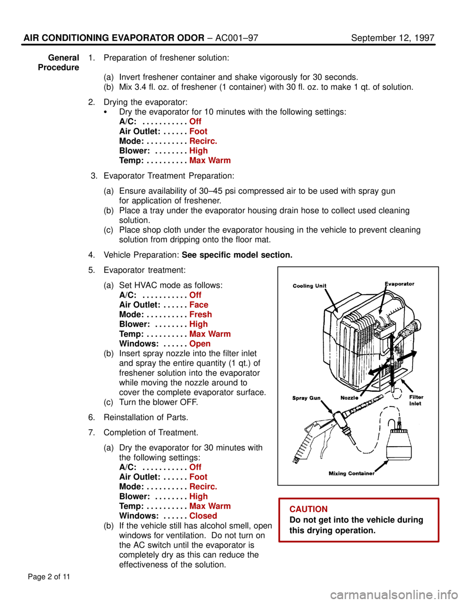
(b) Insert spray nozzle into the filter inlet and spray the entire quantity (1 qt.) of
freshener solution into the evaporator
while moving the nozzle around to
cover the complete evaporator surface.
(c) Turn the blower OFF.
6. Reinstallation of Parts.
7. Completion of Treatment. (a) Dry the evaporator for 30 minutes with the following settings:
A/C: Off
. . . . . . . . . . .
Air Outlet: Foot
. . . . . .
Mode: Recirc.
. . . . . . . . . .
Blower: High
. . . . . . . .
Te m p : Max Warm
. . . . . . . . . .
Windows: Closed
. . . . . .
(b) If the vehicle still has alcohol smell, open windows for ventilation. Do not turn on
the AC switch until the evaporator is
completely dry as this can reduce the
effectiveness of the solution.
Page 2 of 11
CAUTION
Do not get into the vehicle during
this drying operation.
WhereEverybodyKnowsYourName