Page 1948 of 4087
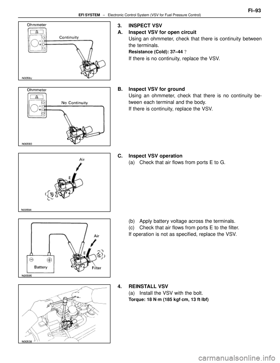
3. INSPECT VSV
A. Inspect VSV for open circuitUsing an ohmmeter, check that there is continuity between
the terminals.
Resistance (Cold): 37±44 �
If there is no continuity, replace the VSV.
B. Inspect VSV for ground Using an ohmmeter, check that there is no continuity be-
tween each terminal and the body.
If there is continuity, replace the VSV.
C. Inspect VSV operation (a) Check that air flows from ports E to G.
(b) Apply battery voltage across the terminals.
(c) Check that air flows from ports E to the filter.
If operation is not as specified, replace the VSV.
4. REINSTALL VSV (a) Install the VSV with the bolt.
Torque: 18 N Vm (185 kgf Vcm, 13 ft Vlbf)
FI±93EFI SYSTEM ± Electronic Control System (VSV for Fuel Pressure Control)
WhereEverybodyKnowsYourName
Page 2007 of 4087

AIR INDUCTION SYSTEM
Air filtered through the air cleaner passes through the air flow meter a\
nd the amount flowing to the air intake
chamber is determined by the throttle valve opening in the throttle body and th\
e engine rpm.
Air flow meter measures the air intake flow to the engine by the swirl f\
requency.
Located in the throttle body is the throttle valve, which regulates the \
volume of air intake to the engine. Air
intake controlled by the throttle valve opening is distributed from the \
intake chamber to the manifold of each
cylinder and is drain into the combustion chamber.
At low air temperature the ISC valve opens and the air flows through the I\
SC valve, as well as the throttle body,
into the air intake chamber. During engine warm up, the fast idle is accomplished by air flowing into the intake
chamber via ISC valve, even when the throttle valve is completely closed.
The air intake chamber prevents pulsation of the intake air, reduces the influence on the air flow meter and
increases the air intake volume. It also prevents intake air interferenc\
e in each cylinder.
There is also the Int ake Air Control Valve (IACV) attached to the air intake chamber. Part of the Acoustic Control
Induction System (ACIS), the ECU provides signals to the Vacuum Switch Valve (VSV) to open or close. This
valve opens or closes, the vacuum source to the actuator, which in turn opens or closes the IACV. The IACV
is designed to modify the effective manifold length in two stages for increased power in all driving\
ranges.
±
EFI SYSTEM OperationFI±7
WhereEverybodyKnowsYourName
Page 2011 of 4087

FUEL SYSTEM
Fuel is pumped up by the fuel pump, which flows through the fuel filter under pr\
essure through the fuel pipe
to the delivery pipe where it is distributed to each injector and the cold\
start injector.
The fuel pressure regulator adjusts the pressure of the fuel from the fuel \
line (high pressure side) to a pres-
sure 284 kPa (2.9 kgf/cm
2, 41 psi) higher than the pressure inside the intake manifold, and exce\
ss fuel is re-
turned to the fuel tank through the return pipe.
When the engine is hot, the fuel pressure is increased to control percolatio\
n in the fuel system and improve
restartability and idling stability.
The pulsation damper absorbs the slight fluctuations in fuel pressure ca\
used by the injector.
The injectors operate on input of injection signals from the ECU and inj\
ect fuel into the intake manifold.
The cold start injector operates when starting with low coolant temperature or at normal temperature
ranges, injecting fuel into the air intake chamber to improve startability. FI±7
EFI SYSTEM
± Operation
WhereEverybodyKnowsYourName
Page 2012 of 4087

AIR INDUCTION SYSTEM
Air filtered through the air cleaner passes through the air flow meter and \
the amount flowing to the air intake
chamber is determined according to the throttle valve opening in the throttle b\
ody and the engine rpm. Air flow meter measures the air intake flow to the engine by the swirl f\
requency.
Located in the throttle body is the throttle valve, which regulates the volume \
of air intake to the engine. Air
intake controlled by the throttle valve opening is distributed from the intake\
chamber to the manifold of each
cylinder and is drain into the combustion chamber. At air low temperature the ISC valve opens and the air flows through the I\
SC valve, as well as the throttle
body, into the air intake chamber. During engine warming up, even if the throttle valve is completely clo\
sed, air
flows to the air intake chamber, thereby increasing the idle speed (first idle operation). The air intake chamber prevents pulsation of the intake air, reduces the influence on the air flow meter and
increases the air intake volume. It also prevents intake air interference in each\
cylinder. FI±8
EFI SYSTEM ± Operation
WhereEverybodyKnowsYourName
Page 2075 of 4087
PRECAUTIONS
1. Always use new gaskets when replacing the fuel tank orcomponent part.
2. Apply the proper torque to all parts tightened.
INSPECTION OF FUEL LINES AND
CONNECTIONS
(a) Inspect the fuel lines and connections for cracks,
leakage or deformation.
(b) Inspect the fuel tank vapor vent system hoses and connections for looseness, kinks or damage.
(c) Inspect the fuel tank for deformation, cra cks, fuel
leakage or tank band looseness.
(d) Check the filter neck for damage or fuel leakage.
(e) Ho se an d tu b e c onnections are as shown in the
illustration.
If a problem is found, repair or replace the parts as necessary.
FI±38
±
EFI SYSTEM REPAIR INSTRUCTIONS
WhereEverybodyKnowsYourName
Page 2123 of 4087

A pressure feeding lubrication system has been adopted to supply oil to \
the moving parts of this engine. The
lubrication system consists of an oil pan, oil pump, oil filter and other external p\
arts which supply oil to the moving
parts in the engine block. The oil circuit is shown in the illustration at th\
e top of the previous page. Oil from the
oil pan is pumped up by the oil pump. After it passes through the oil fi\
lter, it is fed through the various oil holes
in the crankshaft and cylinder block. After passing through the cylinder b\
lock and performing its lubricating func-
tion, the oil is returned by gravity to the oil pan. A dipstick on the center\
left side of the cylinder block is provided
to check the oil level.
OIL PUMP The oil pump pumps up oil from the oil pan and sends it under pressure to t\
he various parts of the engine.
An oil strainer is mounted in front of the inlet to the oil pump. The oil \
pump itself is a trochoid type pump, inside
of which there is a drive rotor and a driven rotor. When the drive rotor rotates, the driven rotor rotates in the same
direction, and since the axis of the driven rotor shaft is different from the center of the driven rotor, the space
between the two rotors is changed as they rotate. Oil is drawn in when the space\
is wide and is discharged when
the space in narrow.
OIL PRESSURE REGULATOR At high engine speeds, the engine oil supplied by the oil pump exceeds the\
capacity of the engine to utilize
it. For that reason, the oil pressure regulator works to prevent an over\
supply of oil. During normal oil supply, a
coil spring and valve keep the bypass closed, but when too much oil is being \
fed, the pressure become extremely
high, overpowering the force of the spring and opening the valves. This allow\
s the excess oil to flow through
the valve and return to the oil pump inlet.
OIL FILTER The oil filter is a full flow type filter with a built±in paper filter e\
lement. Particles of metal from wear, airborne
dirt, carbon and other impurities can get into the oil during use and co\
uld cause accelerated wear or seizing if
allowed to circulate through the engine. The oil filter, integrated into the oil line, removes these impurities as the
oil passes through it. The filter is mounted outside the engine to simplify\
replacement of the filter element. A relief
valve is also included ahead of the filter element to relieve the high oil pr\
essure in case the filter element be-
comes clogged with impurities. The relief valve opens when the oil pressure o\
verpowers the force of the spring.
Oil passing through the relief valve by±passes the oil filter and flo\
ws directly into the main oil hole in the engine.
±
LUBRICATION SYSTEM PrecautionsLU±3
WhereEverybodyKnowsYourName
Page 2158 of 4087
wAfter installing a drive belt, check that it fits properly in
the ribbed grooves.
w Check by hand to confirm that the belt has not slipped
out of the groove on the bottom of the pulley.
3. INSPECT AIR FILTER
(a) Open the air cleaner cap.
(b) Remove the air filter.
(c) Visually check that the air filter is not excessively damaged or oily.
If necessary, replace the air filter.
(d) Clean the air filter with compressed air. First blow from the inside thoroughly, then blow off from the
outside of the air filter.
(e) Reinstall the air filter and air cleaner cap.
4. REPLACE AIR FILTER Replace the air filter with a new one.
±
MAINTENANCE (1UZ ± FE)MA±7
WhereEverybodyKnowsYourName
Page 2160 of 4087

Oil grade:
API grade SG or SH, Energy±Conserving II or ILSAC
multigrade engine oil. Recommended viscosity is as
shown i")
6. REPLACE ENGINE OIL AND OIL FILTER(See Lubrication System on page EG±497)
Oil grade:
API grade SG or SH, Energy±Conserving II or ILSAC
multigrade engine oil. Recommended viscosity is as
shown in the illustration, with SAE 5W±30 being the
preferred engine oil.
Drain and refill capacity:
w/ Oil filter change
4.8 liters (5.1 US qts, 4.2 lmp. qts)
w/o Oil filter change
4.5 liters (4.8 US qts, 4.0 lmp. qts)
7. REPLACE ENGINE COOLANT (See Cooling System on page EG±425)
Coolant capacity (w/ Heater):
10.8 liters (11.4 US qts, 9.5 lmp. qts)
HINT:
wUse a good brand of ethylene±glycol base coolant and
mix it according to the manufacturer's directions.
w Using coolant which includes more than 50 %
ethylene±glycol (but not more than 70 %) is
recommended.
NOTICE:
w Do not use a alcohol type coolant.
w The coolant should be mixed with demineralized water or
distilled water.
8. INSPECT CHARCOAL CANISTER
(a) Remove the charcoal canister.
(See Emission Control System on page EG±221)
(b) Visually inspect the canister case.
(c) Check for crogged each port and stuck check valve. wUsing low compressed air (4.71 kPa (48 gf/cm
2, 0.68
psi)), blow into port A and check that air flows without
resistance from the other ports.
w Blow low compressed air (4.71 kPa (48 gf/cm
2, 0.68
psi)) into port B and check that air does not flow from the
other ports.
If operation is not as specified, replace the charcoal canister.
±
MAINTENANCE (1UZ ± FE)MA±9
WhereEverybodyKnowsYourName
 Inspect the fue")
