Page 244 of 4087

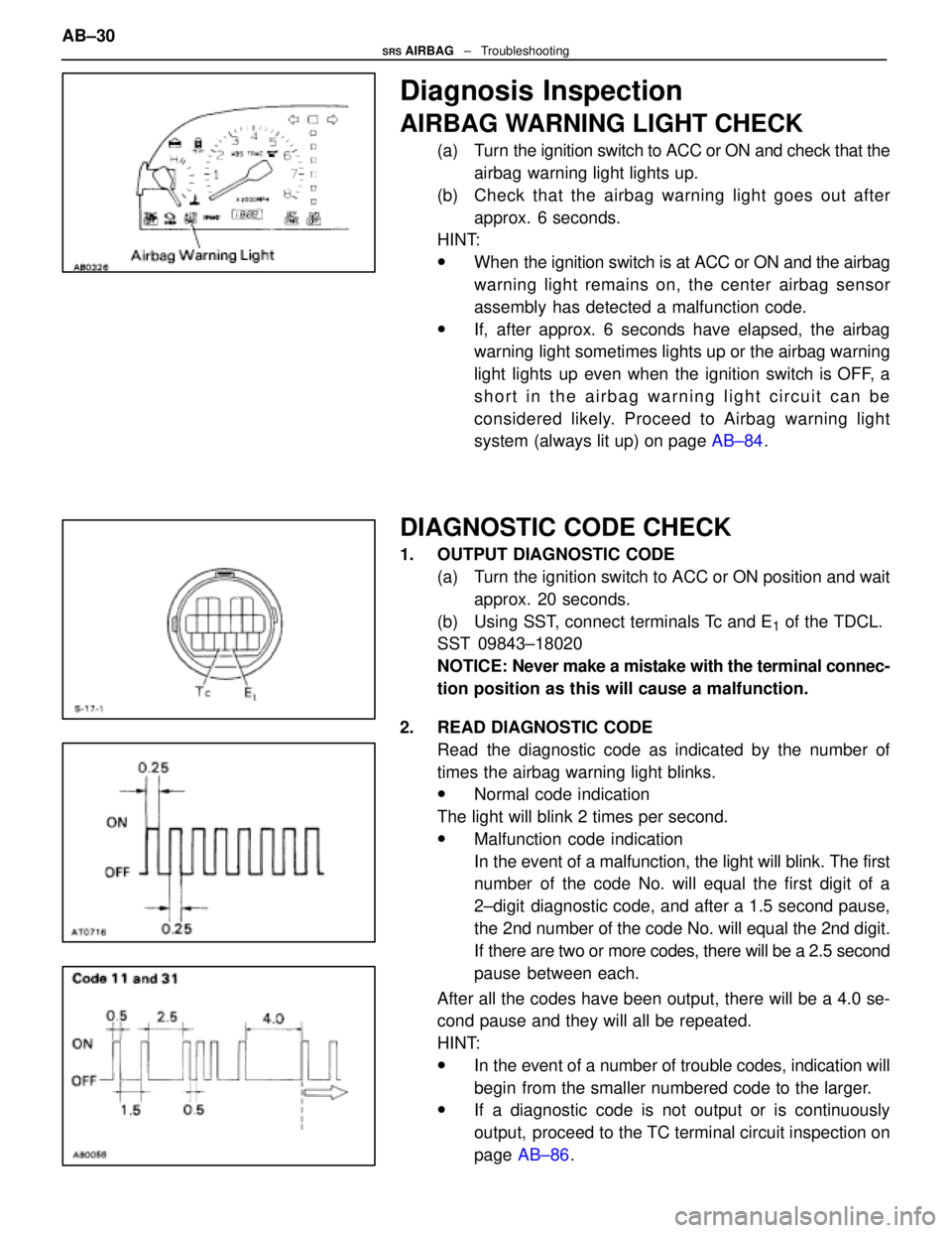
Diagnosis Inspection
AIRBAG WARNING LIGHT CHECK
(a) Turn the ignition switch to ACC or ON and check that theairbag warning light lights up.
(b) Check that the airbag warning light goes out after approx. 6 seconds.
HINT:
wWhen the ignition switch is at ACC or ON and the airbag
warning light remains on, the center airbag sensor
assembly has detected a malfunction code.
wIf, after approx. 6 seconds have elapsed, the airbag
warning light sometimes lights up or the airbag warning
light lights up even when the ignition switch is OFF, a
short in the airbag warning light circuit can be
considered likely. Proceed to Airbag warning light
system (always lit up) on page AB±84.
DIAGNOSTIC CODE CHECK
1. OUTPUT DIAGNOSTIC CODE
(a) Turn the ignition switch to ACC or ON position and waitapprox. 20 seconds.
(b) Using SST, connect terminals Tc and E
1 of the TDCL.
SST 09843±18020
NOTICE: Never make a mistake with the terminal connec-
tion position as this will cause a malfunction.
2. READ DIAGNOSTIC CODE Read the diagnostic code as indicated by the number of
times the airbag warning light blinks.
wNormal code indication
The light will blink 2 times per second.
wMalfunction code indication
In the event of a malfunction, the light will blink. The first
number of the code No. will equal the first digit of a
2±digit diagnostic code, and after a 1.5 second pause,
the 2nd number of the code No. will equal the 2nd digit.
If there are two or more codes, there will be a 2.5 second
pause between each.
After all the codes have been output, there will be a 4.0 se-
cond pause and they will all be repeated.
HINT:
wIn the event of a number of trouble codes, indication will
begin from the smaller numbered code to the larger.
wIf a diagnostic code is not output or is continuously
output, proceed to the TC terminal circuit inspection on
page AB±86 .
AB±30
SRS AIRBAG
± Troubleshooting
WhereEverybodyKnowsYourName
Page 248 of 4087

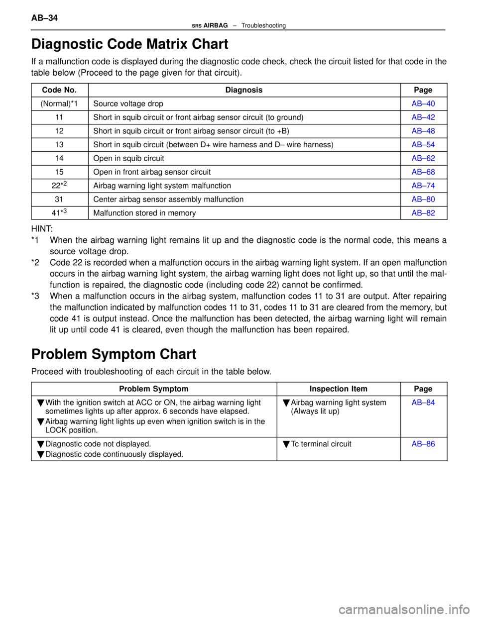
Diagnostic Code Matrix Chart
If a malfunction code is displayed during the diagnostic code check, check\
the circuit listed for that code in the
table below (Proceed to the page given for that circuit).
Code No.DiagnosisPage
(Normal)*1Source voltage dropAB±40
11Short in squib circuit or front airbag sensor circuit (to ground)AB±42
12Short in squib circuit or front airbag sensor circuit (to +B)AB±48
13Short in squib circuit (between D+ wire harness and D± wire harness)\
AB±54
14Open in squib circuitAB±62
15Open in front airbag sensor circuitAB±68
22*2Airbag warning light system malfunctionAB±74
31Center airbag sensor assembly malfunctionAB±80
41*3Malfunction stored in memoryAB±82
HINT:
*1 When the airbag warning light remains lit up and the diagnostic code is the normal code, this means asource voltage drop.
*2 Code 22 is recorded when a malfunction occurs in the airbag warning light sy\
stem. If an open malfunction occurs in the airbag warning light system, the airbag warning light does not light up, so that until the mal-
function is repaired, the diagnostic code (including code 22) cannot be confir\
med.
*3 When a malfunction occurs in the airbag system, malfunction codes 11 to 31 are output. After repairing the malfunction indicated by malfunction codes 11 to 31, codes 11 to 31 are cleared from the memory, but
code 41 is output instead. Once the malfunction has been detected, the airba\
g warning light will remain
lit up until code 41 is cleared, even though the malfunction has been re\
paired.
Problem Symptom Chart
Proceed with troubleshooting of each circuit in the table below.
Problem SymptomInspection ItemPage
�With the ignition switch at ACC or ON, the airbag warning light
sometimes lights up after approx. 6 seconds have elapsed.
� Airbag warning light lights up even when ignition switch is in the
LOCK position.�Airbag warning light system
(Always lit up)AB±84
�Diagnostic code not displayed.
� Diagnostic code continuously displayed.�Tc terminal circuitAB±86
AB±34SRS AIRBAG ± Troubleshooting
WhereEverybodyKnowsYourName
Page 278 of 4087

DIAGNOSIS SYSTEM
AT09R±07
The electronically controlled transmission system has built±
in self±diagnostic functions. If the malfunction occurs in the
system, the ECM stores the malfunction code in memory and
the O/D OFF (Overdrive OFF) indicator light blinks to inform
the driver. The diagnostic trouble code stored in memory can
be read out by the following procedure.
O/D OFF INDICATOR LIGHT INSPECTION
AT09S±07
1. Turn the ignition switch to ON.
2. Check if the O/D OFF indicator light lights up when the O/D main switch is pushed out to OFF and goes off when
the O/D main switch is pushed in to ON.
HINT:
wIf the O/D OFF indicator light does not light up or stay on
all the time, carry out the check for ªO/D OFF Indicator
Light Circuitº on page AT±112.
w If the O/D OFF indicator light blinks, a trouble code is
stored in the ECM memory.
DIAGNOSTIC TROUBLE CODE CHECK
AT0A3±07
1. Turn the ignition switch ON, but do not start the engine.
2. Push in the O/D main switch to ON.
HINT: Warning and diagnostic trouble codes can be r ead only
when the O/D main switch is ON. If it is OFF, the O/D OFF indi-
cator lights up continuously and will not blink.
3. Using SST, connect terminals TE1 and E1 of the DLC2 or
DLC1.
SST 09843±18020
±
A304E (1UZ±FE) AUTOMATIC TRANSMISSION TROUBLESHOOTINGAT±37
WhereEverybodyKnowsYourName
Page 349 of 4087
OKNG
OKNG
OKNG
INSPECTION PROCEDURE
1Check operation of stop light.
Check if the stop lights go on and off normally when the brake pedal is operated and released.C
Check and repair stop light circuit (See BE section).
2Check stop light signal.
C
OK
1. Connect voltmeter to the terminals TT and E1 of the
DLC2.
2. Turn ignition switch ON (Do not start the engine).
3. Fully depress the accelerator pedal until the volt- meter indicates 8 V and hold it.
4. Depress and release the brake pedal and check the
voltage.
Proceed to next circuit inspection shown on matrix chart
(See page AT±66).
3Check harness and connector between ECM and stop light switch (See page\
IN±33).
Repair or replace harness or connector.
Check and replace ECM.
±
A304E (1UZ±FE) AUTOMATIC TRANSMISSION TROUBLESHOOTINGAT±109
WhereEverybodyKnowsYourName
Page 352 of 4087
WIRING DIAGRAM
O/D Main Switch and O/D OFF Indicator Light Circuit
CIRCUIT DESCRIPTION
The O/D main switch contacts go off when the switch is pushed in and comes on when it is pushed out.
In O/D main switch OFF position, the O/D OFF indicator lights up, and the \
ECM prohibits shifting to over-
drive. The ECM also causes the O/D OFF indicator light to blink when a malfunc\
tion is detected. In this
case, connecting the terminals in the DLC2 or DLC1 can display the malfu\
nction code.
DIAGNOSTIC CHARTDIAGNOSTIC CHART
See next page.
AT±112
±
A304E (1UZ±FE) AUTOMATIC TRANSMISSION TROUBLESHOOTING
WhereEverybodyKnowsYourName
Page 354 of 4087

OKNG
OKNG
OKNG
INSPECTION PROCEDURE
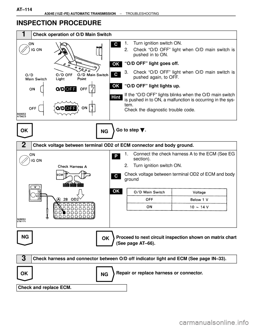
1Check operation of O/D Main Switch
C
OK
Hint
C
OK
1. Turn ignition switch ON.
2. Check ªO/D OFFº light when O/D main switch ispushed in to ON.
ªO/D OFFº light goes off.
3. Check ªO/D OFFº light when O/D main switch is pushed again, to OFF.
ªO/D OFFº light lights up.
If the ªO/D OFFº lights blinks when the O/D main switch
is pushed in to ON, a malfunction is occurring in the sys-
tem.
Check the diagnostic trouble code.
Go to step �.
2Check voltage between terminal OD2 of ECM connector and body ground.
C
OK
P1. Connect the check harness A to the ECM (See EG
section).
2. Turn ignition switch ON.
Check voltage between terminal OD2 of ECM and body
ground
Proceed to next circuit inspection shown on matrix chart
(See page AT±66).
3Check harness and connector between O/D off indicator light and ECM (Se\
e page IN±33).
Repair or replace harness or connector.
Check and replace ECM.
AT±114±
A304E (1UZ±FE) AUTOMATIC TRANSMISSION TROUBLESHOOTING
WhereEverybodyKnowsYourName
Page 508 of 4087
INSTALLATION OF FRONT BUMPER
(See page BO±11)
INSTALL FRONT BUMPER PARTS BY FOLLOWING RE-
MOVAL SEQUENCE IN REVERSE HINT:
wWhen installing the bumper on the body, be careful
not to damage the serrated part of side bolts.
wAfter installing the headlight, adjust the light aiming.
(See page BE±38).
DISASSEMBLY AND ASSEMBLY OF
FRONT BUMPER
DISASSEMBLY AND ASSEMBLY BY
FOLLOWING PARTS:
(a) Cornering lights
(b) Side turn lights
(c) Bumper energy absorber
(d) Retainers
(e) License bracket
BO±14
±
BODY Bumper (Front Bumper)
WhereEverybodyKnowsYourName
Page 537 of 4087

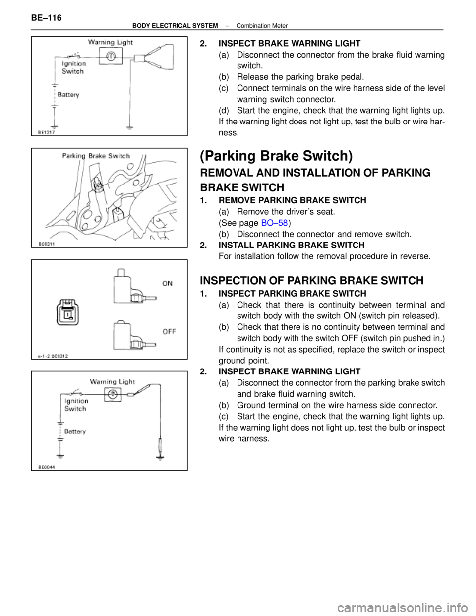
2. INSPECT BRAKE WARNING LIGHT(a) Disconnect the connector from the brake fluid warningswitch.
(b) Release the parking brake pedal.
(c) Connect terminals on the wire harness side of the level warning switch connector.
(d) Start the engine, check that the warning light lights up.
If the warning light does not light up, test the bulb or wire har-
ness.
(Parking Brake Switch)
REMOVAL AND INSTALLATION OF PARKING
BRAKE SWITCH
1. REMOVE PARKING BRAKE SWITCH
(a) Remove the driver's seat.
(See page BO±58)
(b) Disconnect the connector and remove switch.
2. INSTALL PARKING BRAKE SWITCH For installation follow the removal procedure in reverse.
INSPECTION OF PARKING BRAKE SWITCH
1. INSPECT PARKING BRAKE SWITCH
(a) Check that there is continuity between terminal andswitch body with the switch ON (switch pin released).
(b) Check that there is no continuity between terminal and switch body with the switch OFF (switch pin pushed in.)
If continuity is not as specified, replace the switch or inspect
ground point.
2. INSPECT BRAKE WARNING LIGHT (a) Disconnect the connector from the parking brake switchand brake fluid warning switch.
(b) Ground terminal on the wire harness side connector.
(c) Start the engine, check that the warning light lights up.
If the warning light does not light up, test the bulb or inspect
wire harness.
BE±116
±
BODY ELECTRICAL SYSTEM Combination Meter
WhereEverybodyKnowsYourName