Page 7 of 4087

IDENTIFICATION INFORMATION
VEHICLE IDENTIFICATION NUMBER
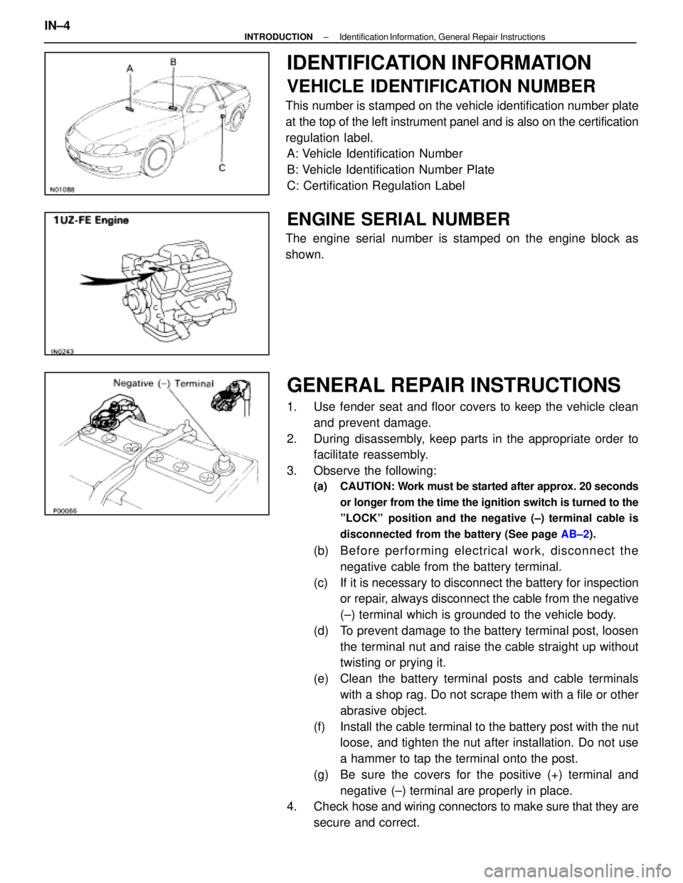
This number is stamped on the vehicle identification number plate
at the top of the left instrument panel and is also on the certification
regulation label.A: Vehicle Identification Number
B: Vehicle Identification Number Plate
C: Certification Regulation Label
ENGINE SERIAL NUMBER
The engine serial number is stamped on the engine block as
shown.
GENERAL REPAIR INSTRUCTIONS
1. Use fender seat and floor covers to keep the vehicle clean
and prevent damage.
2. During disassembly, keep parts in the appropriate order to facilitate reassembly.
3. Observe the following:
(a) CAUTION: W ork must be started after approx. 20 seconds
or longer from the time the ignition switch is turned to the
ºLOCKº position and the negative (±) terminal cable is
disconnected from the battery (See page AB±2).
(b) B e fo re pe rfo rmin g ele ctrica l wo rk, disc onnect the
negative cable from the battery terminal.
(c) If it is necessary to disconnect the battery for inspection or repair, always disconnect the cable from the negative
(±) terminal which is grounded to the vehicle body.
(d) To prevent damage to the battery terminal post, loosen the terminal nut and raise the cable straight up without
twisting or prying it.
(e) Clean the battery terminal posts and cable terminals with a shop rag. Do not scrape them with a file or other
abrasive object.
(f) Install the cable terminal to the battery post with the nut loose, and tighten the nut after installation. Do not use
a hammer to tap the terminal onto the post.
(g) Be sure the covers for the positive (+) terminal and negative (±) terminal are properly in place.
4. Check hose and wiring connectors to make sure that they are
secure and correct.
IN±4
±
INTRODUCTION Identification Information, General Repair Instructions
WhereEverybodyKnowsYourName
Page 10 of 4087

TOTAL DIAGNOSTIC
COMMUNICATION LINK (TDCL)
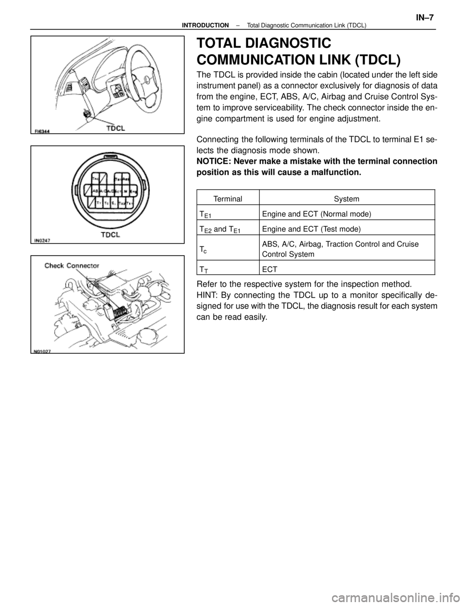
The TDCL is provided inside the cabin (located under the left side
instrument panel) as a connector exclusively for diagnosis of data
from the engine, ECT, ABS, A/C, Airbag and Cruise Control Sys-
tem to improve serviceability. The check connector inside the en-
gine compartment is used for engine adjustment.
Connecting the following terminals of the TDCL to terminal E1 se-
lects the diagnosis mode shown.
NOTICE: Never make a mistake with the terminal connection
position as this will cause a malfunction.
TerminalSystem
TE1Engine and ECT (Normal mode)
TE2 and TE1Engine and ECT (Test mode)
TcABS, A/C, Airbag, Traction Control and Cruise
Control System
TTECT
Refer to the respective system for the inspection method.
HINT: By connecting the TDCL up to a monitor specifically de-
signed for use with the TDCL, the diagnosis result for each system
can be read easily.
±
INTRODUCTION Total Diagnostic Communication Link (TDCL)IN±7
WhereEverybodyKnowsYourName
Page 79 of 4087
LOCATION OF CONNECTORS IN INSTRUMENT PANEL
AC±40±
AIR CONDITIONING SYSTEM Troubleshooting
WhereEverybodyKnowsYourName
Page 81 of 4087
LOCATION OF CONNECTORS IN INSTRUMENT PANEL
AC±42±
AIR CONDITIONING SYSTEM Troubleshooting
WhereEverybodyKnowsYourName
Page 84 of 4087

Check voltage between terminals TR and SG of air conditioner control
assembly connector.
(1) Remove console upper panel. (See page BO-111 )
(2) Remove A/C Control Assembly with connectors
still connected.
(3) Turn ignition switch ON.
Check voltage between terminals TAM and SG of air
conditioner control assembly connector at each tem-
perature.
Voltage
at 25°C (77°F) : 1.8~2.2 V
at 40°C (104°F) : 1.2~1.6 V
In addition, as the temperature increases, the
voltage decreases gradually.
Proceed to next circuit inspection shown on
matrix chart (See page AC-36).However,
when Diag. code 11 is displayed, check and
replace air conditioner control assembly.
Check room temperature sensor.
(1) Remove instrument finish lower No. 1 panel.
(See page Be-103).
Resistance
at 25°C (77°F) : 1.6~1.8k �
at 50°C (122°F) : 0.5~0.7k�
In addition, as the temperature increases, the
voltage decreases gradually.
Replace room temperature sensor.
Check for open and short in harness and connector between air conditioner
control assembly and room temperature sensor (See page IN-27).
Repair or replace harness or connector.
Check and repair air conditioner control
assembly.
(2) Disconnect room0 temperature sensor
connector.
Check voltage between terminals 1 and 2 of
room temperature sensor connector at each tem±
perature.
INSPECTION PROCEDURE
±
AIR CONDITIONING SYSTEM TroubleshootingAC±45
WhereEverybodyKnowsYourName
Page 144 of 4087
A/C UNIT
REMOVAL OF A/C UNIT
1. RECOVER REFRIGERANT IN SYSTEMSee page AC±16
2. REMOVE ENGINE See page EM±118
3. REMOVE WATER VALVE
See page AC±127
4. REMOVE BRAKE TUBES BRACKET MOUNTING BOLTS FROM DUSH PANEL
5. REMOVE EVAPORATOR See page AC±122
6. REMOVE WATER HOSE FROM HEATER RADIATOR
7. REMOVE INSULATOR RETAINER Remove the two bolts and the retainer.
8. REMOVE INSTRUMENT PANEL REINFORCEMENT See page BO±109
9. REMOVE FLOOR CARPET See page BO±118
10. REMOVE REAR AIR DUCTS Remove the nut and the air duct.
11. REMOVE HEATER TO RESISTER NO. 3 DUCT Remove the screw and the duct.
±
AIR CONDITIONING SYSTEM A/C UnitAC±107
WhereEverybodyKnowsYourName
Page 146 of 4087
9. INSTALL EVAPORATORSee page AC±124
10. INSTALL INSTRUMENT PANEL REINFORCEMENT
11. INSTALL ENGINE See page EM±167
12. E V ACUATE AIR IN REFRIGERATION SYSTEM AND
CHARGE WITH REFRIGERANT
See page AC±17
Specified amount: 950 + 50 g (33.44 + 1.76 oz)
13. INSPECT FOR LEAKAGE OF REFRIGERANT
Using a gas leak tester, check for leakage of refrigerant.
±
AIR CONDITIONING SYSTEM TroubleshootingAC±109
WhereEverybodyKnowsYourName
Page 167 of 4087
AIR INLET SERVOMOTOR
REMOVAL OF AIR INLET SERVOMOTOR
1. REMOVE INSTRUMENT PANEL REINFORCEMENTSee page BO±109
2. REMOVE SERVOMOTOR (a) Disconnect the connector.
(b) Disconnect the control link.
(c) Remove the three screws and the servomotor.
INSPECTION OF AIR INLET
SERVOMOTOR
See page AC±64
AIR INLET SERVOMOTOR
INSTALLATION
1. INSTALL SERVOMOTOR
(a) Install the servomotor with three screws.
(b) Connect the control link.
(c) Connect the connector.
2. INSTALL INSTRUMENT PANEL REIFORCEMENT See page BO±109
AC±130
±
AIR CONDITIONING SYSTEM Air Inlet Servomotor
WhereEverybodyKnowsYourName