Page 168 of 4087
AIR OUTLET SERVOMOTOR
REMOVAL OF AIR OUTLET
SERVOMOTOR
1. REMOVE INSTRUMENT PANEL REINFORCEMENTSee page BO±109
2. REMOVE SERVOMOTOR
(a) Disconnect the connector.
(b) Remove the four screws and the servomotor.
INSPECTION OF AIR OUTLET
SERVOMOTOR
See page AC±68
INSTALLATION OF AIR OUTLET
SERVOMOTOR
1. INSTALL SERVOMOTOR
(a) Install the servomotor with four screws.
(b) Connect the connector.
2. INSTALL INSTRUMENT PANEL REINFORCEMENT
See page BO±109
AIR MIX SERVOMOTOR
REMOVAL OF AIR MIX SERVOMOTOR
1. REMOVE A/C UNIT
See page AC±107
2. REMOVE SERVOMOTOR
(a) Disconnect the connector.
(b) Remove the three screws and the servomotor.
INSPECTION OF AIR MIX SERVOMOTOR
See page AC±60
INSTALLATION OF AIR MIX
SERVOMOTOR
1. INSTALL SERVOMOTOR
(a) Install the servomotor with three screws.
(b) Connect the connector.
2. INSTALL A/C UNIT
See page AC±108
±
AIR CONDITIONING SYSTEM Air Outlet Servomotor, Air Mix ServomotorAC±131
WhereEverybodyKnowsYourName
Page 250 of 4087
Location of Connectors
LOCATION OF CONNECTORS IN INSTRUMENT PANEL
AB±36SRS AIRBAG ± Troubleshooting
WhereEverybodyKnowsYourName
Page 315 of 4087
Location of Connectors in Instrument Panel
AT±74±
A304E (1UZ±FE) AUTOMATIC TRANSMISSION TROUBLESHOOTING
WhereEverybodyKnowsYourName
Page 463 of 4087
INSTRUMENT PANEL
COMPONENTS
BO±108±
BODY Instrument Panel
WhereEverybodyKnowsYourName
Page 464 of 4087
COMPONENTS (Cont'd)
HINT: Screw sizes in the illustration on the previous page
are indicated using the code below for removal and installa-
tion of safety pad.mm (in.)
Code
ShapeSizeCodeShapeSizeCodeShapeSize
j = 8
(0.32)
L = 20
(0.79)j = 5
(0.20)
L = 18
(0.71)
j = 8
(0.32)
j = 6
(0.24)
L = 16
(0.63)j = 5
(0.20)
L = 14
(0.55)
j = 6
(0.24)
j = 6
(0.24)
L = 20
(0.79)j = 5
(0.20)
L = 18
(0.71)j = 5
(0.20)
L = 16
(0.63)
j = 6
(0.24)
L = 25
(0.98)
BO6527
±
BODY Instrument PanelBO±109
WhereEverybodyKnowsYourName
Page 465 of 4087

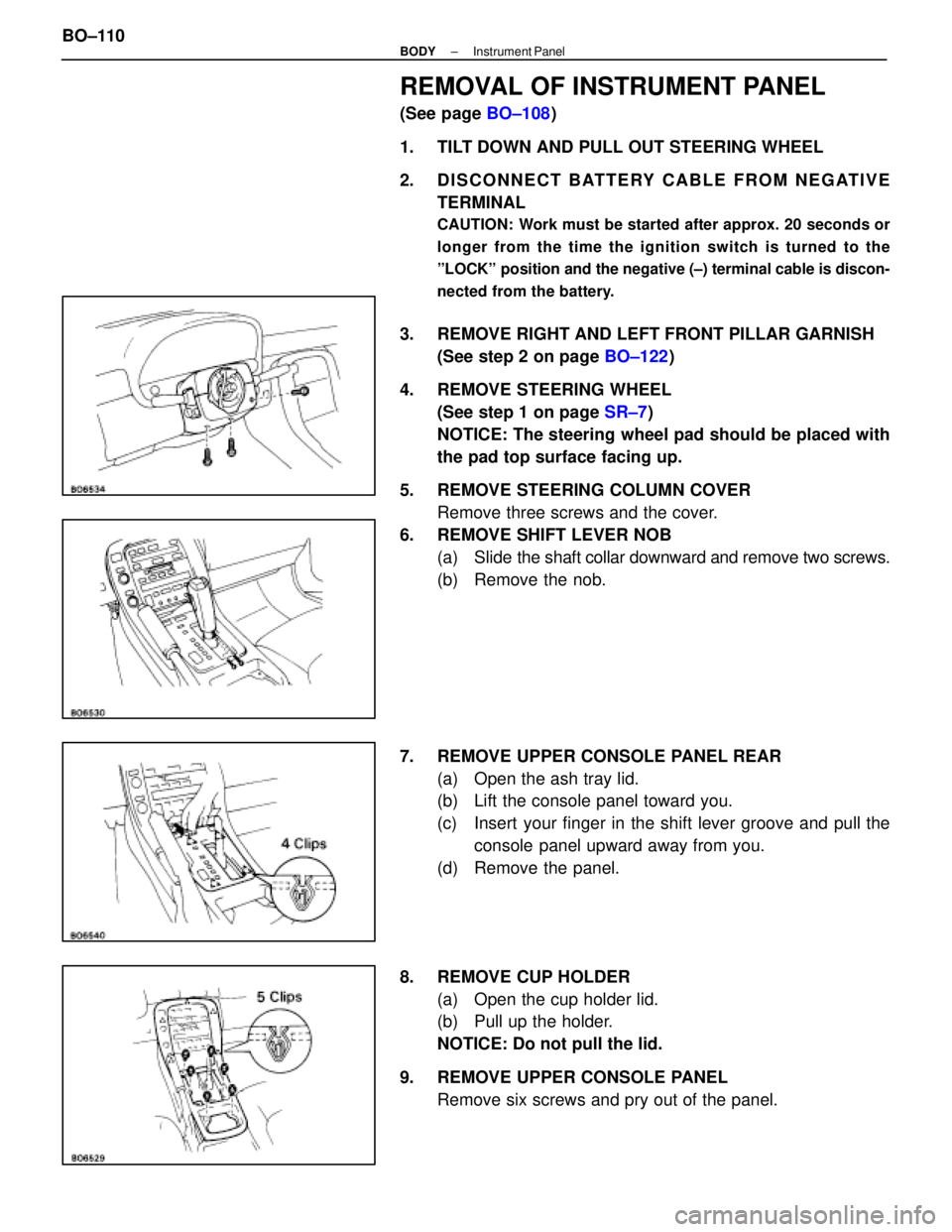
REMOVAL OF INSTRUMENT PANEL
(See page BO±108)
1. TILT DOWN AND PULL OUT STEERING WHEEL
2. DISCONNECT BATTERY CABLE FROM NEGATIVE TERMINAL
CAUTION: Work must be started after approx. 20 seconds or
longer from the time the ignition switch is turned to the
ºLOCKº position and the negative (±) terminal cable is discon-
nected from the battery.
3. REMOVE RIGHT AND LEFT FRONT PILLAR GARNISH(See step 2 on page BO±122)
4. REMOVE STEERING WHEEL (See step 1 on page SR±7)
NOTICE: The steering wheel pad should be placed with
the pad top surface facing up.
5. REMOVE STEERING COLUMN COVER Remove three screws and the cover.
6. REMOVE SHIFT LEVER NOB (a) Slide the shaft collar downward and remove two screws.
(b) Remove the nob.
7. REMOVE UPPER CONSOLE PANEL REAR (a) Open the ash tray lid.
(b) Lift the console panel toward you.
(c) Insert your finger in the shift lever groove and pull theconsole panel upward away from you.
(d) Remove the panel.
8. REMOVE CUP HOLDER (a) Open the cup holder lid.
(b) Pull up the holder.
NOTICE: Do not pull the lid.
9. REMOVE UPPER CONSOLE PANEL Remove six screws and pry out of the panel.
BO±110
±
BODY Instrument Panel
WhereEverybodyKnowsYourName
Page 466 of 4087
10. REMOVE RADIO WITH A/C CONTROL ASSEMBLY(a) Remove six bolts and the radio.
(b) Disconnect the connectors.
11. REMOVE NO. 2 UNDER COVER (a) Using a clip remover, remove two clips.
(b) Remove the cover.
12. REMOVE NO. 2 LOWER FINISH PANEL AND GLOVE COMPARTMENT ASSEMBLY
(a) Remove two caps and two screws.
(b) Remove two screws.
(c) Remove the glove compartment assembly.
13. REMOVE NO. 1 UNDER COVER (a) Remove three screws.
(b) Using the screwdriver, remove the cover.
14. REMOVE CONSOLE BOX Remove five screws, three bolts and the box.
±
BODY Instrument PanelBO±111
WhereEverybodyKnowsYourName
Page 467 of 4087
15. REMOVE CENTER PADUsing a screwdriver, pry out the panel and remove it.
HINT: Tape screwdriver tip before use.
16. REMOVE ENGINE HOOD RELEASE LEVER (a) Remove two screws and the engine hood release lever.
(b) Disconnect the release cable from the lever.
17. REMOVE NO. 1 LOWER FINISH PANEL (a) Using a screwdriver, remove the end pad.
HINT: Tape the screwdriver tip before use.
(b) Remove the bolt and two screws.
(c) Disconnect the connectors and remove the panel.
18. REMOVE COMBINATION SWITCH
19. REMOVE CLUSTER FINISH PANEL Pull out the panel and disconnect the connector.
20. REMOVE COMBINATION METER (a) Remove two caps.
(b) Remove two screws and the meter.
(c) Disconnect the connectors from the meter.
BO±112
±
BODY Instrument Panel
WhereEverybodyKnowsYourName