Page 867 of 4087

Parts Inspection (Turn and Hazard)
(Combination Switch Assembly)
(See page BE±39)
HINT: Inspect turn signal light switch.
(Turn Signal Flasher)
REMOVAL AND INSTALLATION OF TURN
SIGNAL FLASHER
(See page BE±16 )
INSPECTION OF TURN SIGNAL
FLASHER
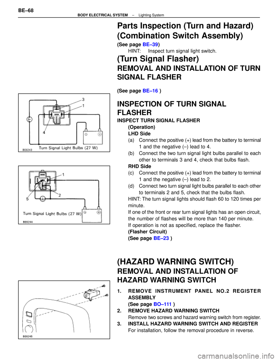
INSPECT TURN SIGNAL FLASHER
(Operation)
LHD Side
(a) Connect the positive (+) lead from the battery to terminal
1 and the negative (±) lead to 4.
(b) Connect the two turn signal light bulbs parallel to each other to terminals 3 and 4, check that bulbs flash.
RHD Side
(c) Connect the positive (+) lead from the battery to terminal
1 and the negative (±) lead to 2.
(d) Connect two turn signal light bulbs parallel to each other
to terminals 2 and 5, check that the bulbs flash.
HINT: The turn signal lights should flash 60 to 120 times per
minute.
If one of the front or rear turn signal lights has an open circuit,
the number of flashes will be more than 140 per minute.
If operation is not as specified, replace the flasher.
(Flasher Circuit)
(See page BE±23 )
(HAZARD WARNING SWITCH)
REMOVAL AND INSTALLATION OF
HAZARD WARNING SWITCH
1. REMOVE INSTRUMENT PANEL NO.2 REGISTER
ASSEMBLY
(See page BO±111 )
2. REMOVE HAZARD WARNING SWITCH Remove two screws and hazard warning switch from register.
3. INSTALL HAZARD WARNING SWITCH AND REGISTER
For installation, follow the removal procedure in reverse.
BE±68
±
BODY ELECTRICAL SYSTEM Lighting System
WhereEverybodyKnowsYourName
Page 902 of 4087
Parts Inspection
(Combination Meter Assembly)
REMOVAL AND INSTALLATION OF
COMBINATION METER ASSEMBLY
1. REMOVE COMBINATION METER ASSEMBLY(a) Lower the steering wheel fully and set it in the far position.
(b) Turn the ignition switch to LOCK and disconnect battery terminals.
CAUTION: Work must be started after approx. 20 se-
conds or longer from the time the ignition switch is
turned to the ºLOCKº position and negative (±) terminal
cable is disconnected from the battery.
(c) Remove instrument cluster finish panel.
(d) Remove four screws and disconnect three connectors.
(e) Remove combination meter assembly.
2. INSTALL COMBINATION METER ASSEMBLY For installation, follow the removal procedure in reverse.
±
BODY ELECTRICAL SYSTEM Combination MeterBE±103
WhereEverybodyKnowsYourName
Page 923 of 4087
Location of Connectors in Instrument Panel
SC300:
±
BRAKE SYSTEM TRACTION CONTROL SYSTEM (TRAC)BR±177
WhereEverybodyKnowsYourName
Page 926 of 4087
Location of Connectors in Instrument Panel
BR±180±
BRAKE SYSTEM TRACTION CONTROL SYSTEM (TRAC)
WhereEverybodyKnowsYourName
Page 1056 of 4087
Location of Connectors in Instrument Panel
±
BRAKE SYSTEM ANTI±LOCK BRAKE SYSTEM (ABS)BR±87
WhereEverybodyKnowsYourName
Page 1058 of 4087
Location of Connectors in Instrument Panel
±
BRAKE SYSTEM ANTI±LOCK BRAKE SYSTEM (ABS)BR±89
WhereEverybodyKnowsYourName
Page 1156 of 4087
LOCATION OF PLASTIC BODY PARTS
Outside Rear View Mirror (ABS)
Instrument Panel Safety Pad (PVC/PUR) Rear Spoiler (SMC)
Front Turn Signal Light (PC/PP)
Center Stop Light (PC)
Mead Light (PC/PP)
Head Light (PC/PP)
Front Bumper Extension
Mounting Bracket (PP)
Quarter Panel
Mud Guard (TPO)
Outside Moulding
Front Fender Mud Guard (TPO)
Front Spoiler (PUR) Cowl Top Ventilation Louver (PP)
Front Bumper Cover (PUR) Side Turn Signal Light (PMMA/ABS)
Cornering Light (PC)
HINT:
wResin material differs with model.
/ Made up of 2 or more kinds of materials.
PLASTIC BODY PARTSPP-4
WhereEverybodyKnowsYourName
Page 1323 of 4087

INSPECTION OF COOLING FAN ECU
1. DISCONNECT CABLE FROM NEGATIVE TERMINAL OFBATTERY
CAUTION: Work must be started after 20 seconds or longer
from the time the ignition switch is turned to the ºLOCKº posi-
tion and the negative (±) terminal cable is disconnected from
the battery.
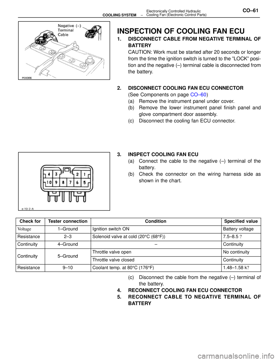
2. DISCONNECT COOLING FAN ECU CONNECTOR (See Components on page CO±60)
(a) Remove the instrument panel under cover.
(b) Remove the lower instrument panel finish panel and glove compartment door assembly.
(c) Disconnect the cooling fan ECU connector.
3. INSPECT COOLING FAN ECU (a) Connect the cable to the negative (±) terminal of thebattery.
(b) Check the connector on the wiring harness side as shown in the chart.
Check forTester connectionConditionSpecified value
Voltage1±GroundIgnition switch ONBattery voltage
Resistance2±3Solenoid valve at cold (20 5C (68 5F))7.5±8.5 �
Continuity4±Ground±Continuity
Continuity5±GroundThrottle valve openNo continuityContinuity5±GroundThrottle valve closedContinuity
Resistance9±10Coolant temp. at 80 5C (176 5F)1.48±1.58 k �
(c) Disconnect the cable from the negative (±) terminal of
the battery.
4. RECONNECT COOLING FAN ECU CONNECTOR
5. RECONNECT CABLE TO NEGATIVE TERMINAL OF BATTERY
±
COOLIING SYSTEM Electronically Controlled Hydraulic
Cooling Fan (Electronic Control Parts)CO±61
WhereEverybodyKnowsYourName