Page 664 of 4087
Location of Connectors in Instrument Panel
BE±280±
BODY ELECTRICAL SYSTEM Power Seat Control System (Driver's Seat)
WhereEverybodyKnowsYourName
Page 702 of 4087
Location of Connectors in Instrument Panel
±
BODY ELECTRICAL SYSTEM Power Seat Control System (Passenger's Seat)BE±321
WhereEverybodyKnowsYourName
Page 741 of 4087
Location of Connectors in Instrument Panel
BE±374±
BODY ELECTRICAL SYSTEM Door Lock Control System
WhereEverybodyKnowsYourName
Page 782 of 4087
Location of Connectors in Instrument Panel
BE±458±
BODY ELECTRICAL SYSTEM Wireless Door Lock Control System
WhereEverybodyKnowsYourName
Page 785 of 4087

OKNG
NGOK
OKNG
OKNG
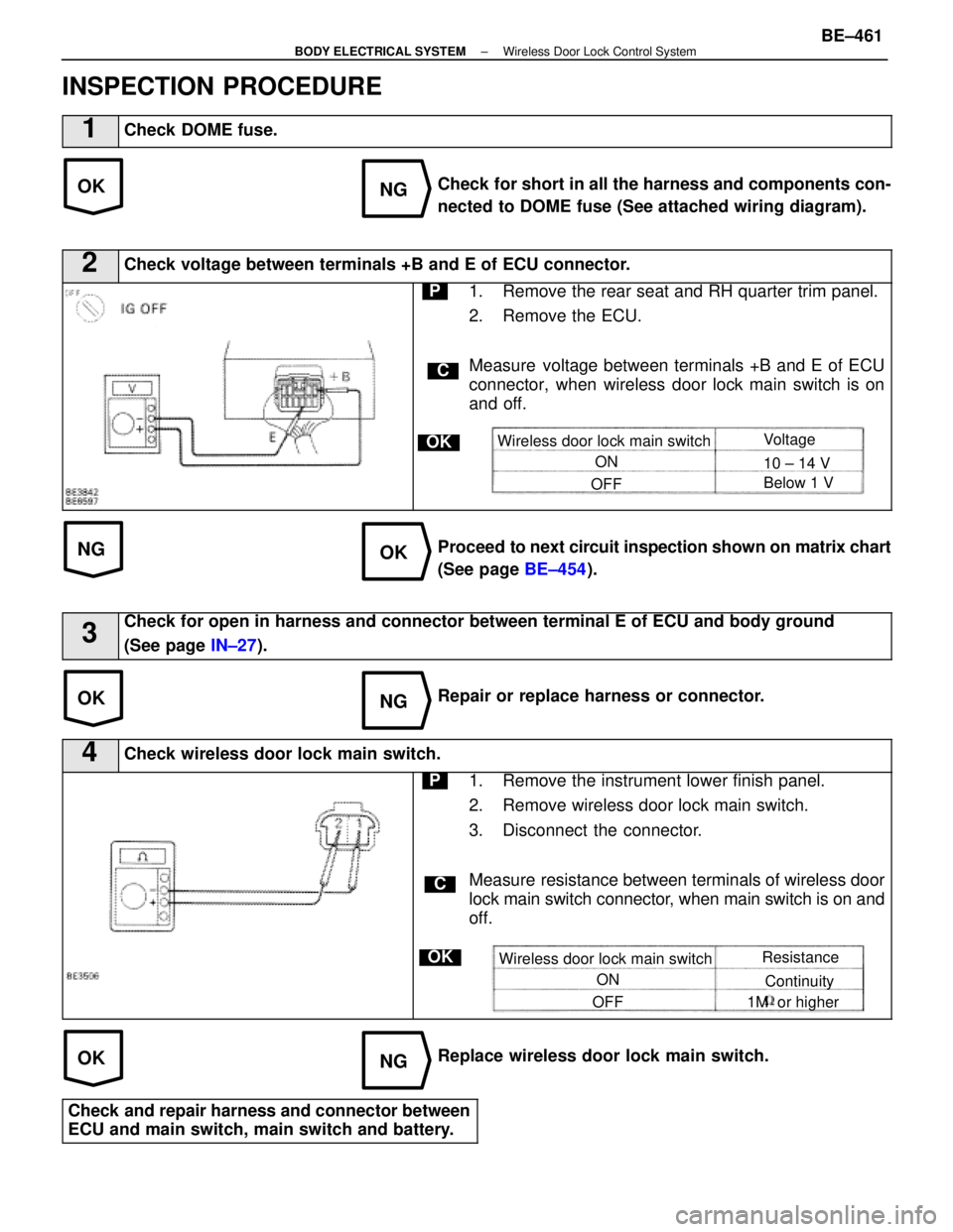
INSPECTION PROCEDURE
1Check DOME fuse.
Check for short in all the harness and components con-
nected to DOME fuse (See attached wiring diagram).
2Check voltage between terminals +B and E of ECU connector.
C
OK
P1. Remove the rear seat and RH quarter trim panel.
2. Remove the ECU.
Measure voltage between terminals +B and E of ECU
connector, when wireless door lock main switch is on
and off.
Wireless door lock main switchON
OFF Voltage
10 ± 14 V
Below 1 V
Proceed to
next circuit inspection shown on matrix chart
(See page BE±454).
3Check for open in harness and connector between terminal E of ECU and bo\
dy ground
(See page IN±27).
Repair or replace harness or connector.
4Check wireless door lock main switch.
C
OK
P1. Remove the instrument lower finish panel.
2. Remove wireless door lock main switch.
3. Disconnect the connector.
Measure resistance between terminals of wireless door
lock main switch connector, when main switch is on and
off.
Wireless door lock main switch
ON
OFF Resistance
Continuity
1M or higher
Replace wireless door lock main switch.
Check and repair harness and connector between
ECU and main switch, main switch and battery.
±
BODY ELECTRICAL SYSTEM Wireless Door Lock Control SystemBE±461
WhereEverybodyKnowsYourName
Page 822 of 4087

Parts Inspection
(Ignition Switch and Key Unlock
Warning Switch)
REMOVAL AND INSTALLATION OF
IGNITION SWITCH AND KEY UNLOCK
WARNING SWITCH
1. DISCONNECT BATTERY TERMINALSCAUTION: Work must be started after approx. 20 se-
conds or longer from the time the ignition switch is
turned to the ºLOCKº position and negative (±) terminal
cable is disconnected from the battery.
2. REMOVE FOLLOWING PARTS: (See page BO±112)
w No. 1 under cover
w No. 1 lower finish panel
w Console box assembly
w Instrument panel lower center
3. REMOVE IGNITION SWITCH (a) Disconnect connector.
(b) Remove three screws and the switch from the keycylinder and wire harness clamp.
4. INSTALL IGNITION SWITCH For installation, follow the removal procedure in reverse.
INSPECTION OF IGNITION SWITCH AND
KEY UNLOCK WARNING SWITCH
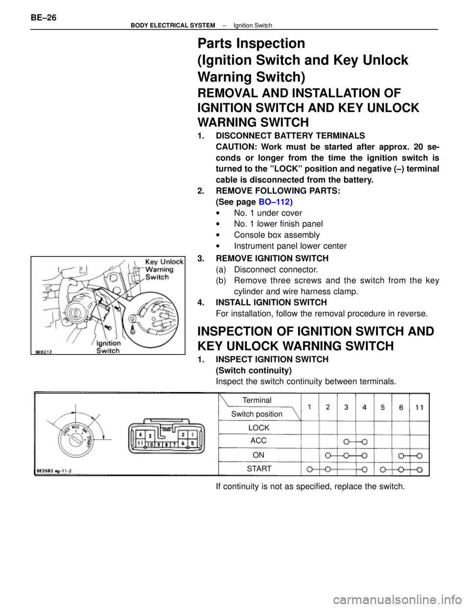
1. INSPECT IGNITION SWITCH(Switch continuity)
Inspect the switch continuity between terminals.
Terminal
Switch position LOCKACC
ON
START
If continuity is not as specified, replace the switch.
BE±26
±
BODY ELECTRICAL SYSTEM Ignition Switch
WhereEverybodyKnowsYourName
Page 848 of 4087
Wiring and Connector Diagrams
Parts Inspection
(Defogger Switch)
REMOVAL AND INSTALLATION OF AIR
CONDITIONER CONTROL PANEL
ASSEMBLY
(See Instrument Panel on Pub. No. RM260U2, page BO±111)
INSPECTION OF DEFOGGER SWITCH
INSPECT SWITCH OPERATION
(a) Connect the positive (+) lead from the battery to terminal A6and negative (±) lead to terminal A7.
(b) Connect the positive (+) lead from the battery to terminal B10
through a 1.4 W test bulb.
BE±52
±
BODY ELECTRICAL SYSTEM Defogger System
WhereEverybodyKnowsYourName
Page 860 of 4087

Parts Replacement ± Stoplights
(Rear Combination Light)
(See page BE±56 )
(High Mount Stop Light)
REPLACEMENT OF HIGH MOUNT STOP
LIGHT
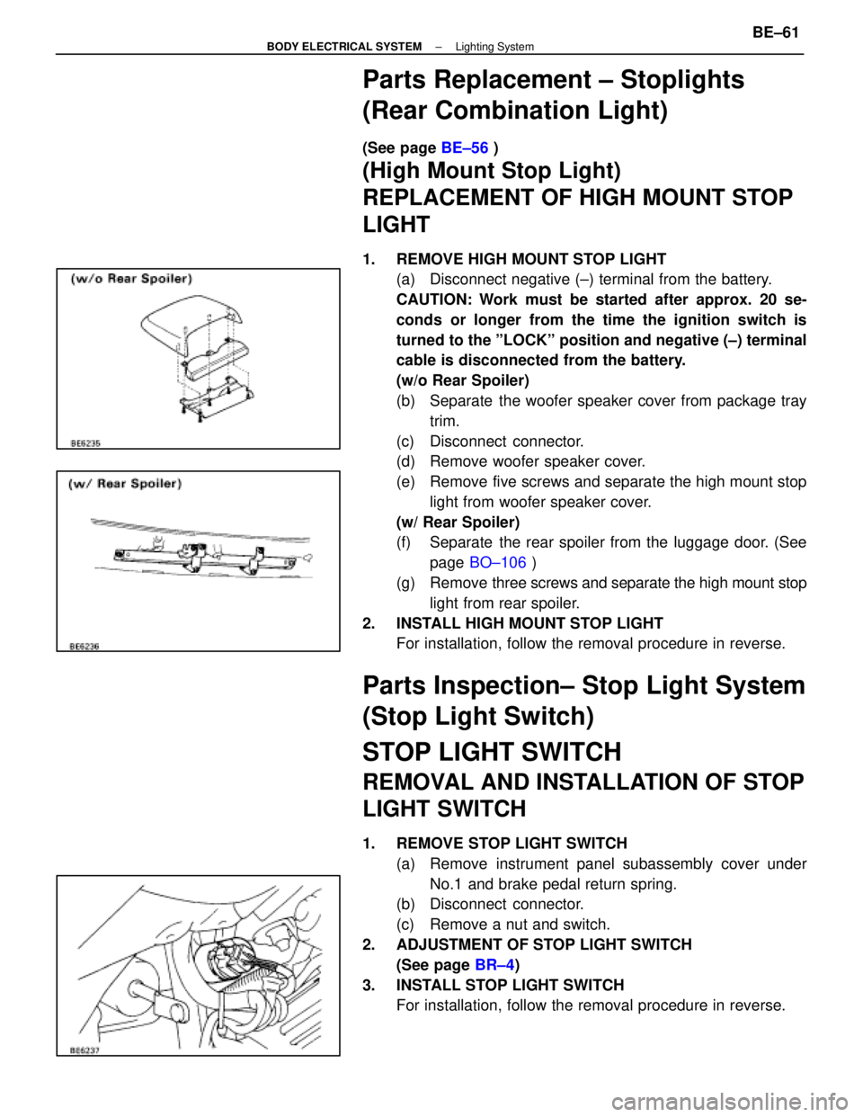
1. REMOVE HIGH MOUNT STOP LIGHT
(a) Disconnect negative (±) terminal from the battery.
CAUTION: Work must be started after approx. 20 se-
conds or longer from the time the ignition switch is
turned to the ºLOCKº position and negative (±) terminal
cable is disconnected from the battery.
(w/o Rear Spoiler)
(b) Separate the woofer speaker cover from package tray
trim.
(c) Disconnect connector.
(d) Remove woofer speaker cover.
(e) Remove five screws and separate the high mount stop light from woofer speaker cover.
(w/ Rear Spoiler)
(f) Separate the rear spoiler from the luggage door. (See page BO±106 )
(g) Remove three screws and separate the high mount stop
light from rear spoiler.
2. INSTALL HIGH MOUNT STOP LIGHT For installation, follow the removal procedure in reverse.
Parts Inspection± Stop Light System
(Stop Light Switch)
STOP LIGHT SWITCH
REMOVAL AND INSTALLATION OF STOP
LIGHT SWITCH
1. REMOVE STOP LIGHT SWITCH
(a) Remove instrument panel subassembly cover underNo.1 and brake pedal return spring.
(b) Disconnect connector.
(c) Remove a nut and switch.
2. ADJUSTMENT OF STOP LIGHT SWITCH (See page BR±4)
3. INSTALL STOP LIGHT SWITCH For installation, follow the removal procedure in reverse.
±
BODY ELECTRICAL SYSTEM Lighting SystemBE±61
WhereEverybodyKnowsYourName