Page 468 of 4087
21. REMOVE KNEE PANEL(a) Remove four bolts.
(b) Remove knee panel.
22. REMOVE NO. 2 HEATER TO REGISTER DUCT Remove the screw and pull out the duct.
23. REMOVE NO. 4 HEATER TO REGISTER DUCT Remove the screw and pull out the duct.
24. REMOVE SAFETY PAD (a) Using a clip remover, remove two clips.
(b) Remove two bolts, three nuts and the safety pad.
±
BODY Instrument PanelBO±113
WhereEverybodyKnowsYourName
Page 469 of 4087
25. REMOVE WIRE HARNESSRemove five screws, clips and the wire harness from the
safety pad.
26. DISASSEMBLY OF SAFETY PADRemove following parts:
(a) Safety pad garnish
(b) No. 1 Instrument panel register
(c) No. 1 Side defroster nozzle
(d) No. 2 Side defroster nozzle
(e) No. 1 Defroster nozzle garnish
(f) No. 2 Defroster nozzle garnish
(g) No. 1 Heater to register duct
(h) No. 5 Heater to register duct
(i) Defroster nozzle
BO±114±
BODY Instrument Panel
WhereEverybodyKnowsYourName
Page 470 of 4087
27. REMOVE INSTRUMENT PANEL REINFORCEMENTRemove four bolts and seven nuts to remove the reinforce-
ment as shown.
INSTALLATION OF INSTRUMENT PANEL
(See page BO±108)
INSTALL INSTRUMENT PANEL PARTS BY FOLLOWING RE-
MOVAL SEQUENCE IN REVERSE HINT: When installing safety pad garnish, after tightening
the wing nuts by hand, use pliers etc. to retighten them.
±
BODY Instrument PanelBO±115
WhereEverybodyKnowsYourName
Page 547 of 4087

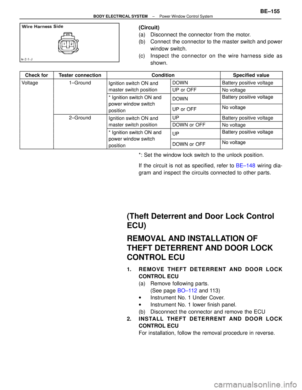
(Circuit)
(a) Disconnect the connector from the motor.
(b) Connect the connector to the master switch and powerwindow switch.
(c) Inspect the c onnector on the wire harness side as
shown.
Check forTester connectionConditionSpecified value
Voltage1±GroundIgnition switch ON andDOWNBattery positive voltagegIgnition switch ON and
master switch positionUP or OFFNo voltage
*Ignition switch ON andDOWNBatterypositive voltage* Ignition switch ON and
power window switch
DOWNBattery ositive voltage
power window switch
iti
UP or OFFNo voltagepositionUP or OFFNo voltage
2±GroundIgnition switch ON andUPBattery positive voltageIgnition switch ON and
master switch positionDOWN or OFFNo voltage
*Ignition switch ON andUPBatterypositive voltage* Ignition switch ON and
power window switch
UPBattery ositive voltage
power window switch
iti
DOWN or OFFNo voltagepositionDOWN or OFFNo voltage
*: Set the window lock switch to the unlock position.
If the circuit is not as specified, refer to BE±148 wiring dia-
gram and inspect the circuits connected to other parts.
(Theft Deterrent and Door Lock Control
ECU)
REMOVAL AND INSTALLATION OF
THEFT DETERRENT AND DOOR LOCK
CONTROL ECU
1. REMOVE THEFT DETERRENT AND DOOR LOCK CONTROL ECU
(a) Remove following parts.(See page BO±112 and 113)
w Instrument No. 1 Under Cover.
w Instrument No. 1 lower finish panel.
(b) Disconnect the connector and remove the ECU
2. INSTALL THEFT DETERRENT AND DOOR LOCK CONTROL ECU
For installation, follow the removal procedure in reverse.
±
BODY ELECTRICAL SYSTEM Power Window Control SystemBE±155
WhereEverybodyKnowsYourName
Page 558 of 4087
Wiring and Connector Diagrams
Parts Inspection
(Defogger Switch)
REMOVAL AND INSTALLATION OF AIR
CONDITIONER CONTROL PANEL
ASSEMBLY
(See Instrument Panel on page BO±111)
INSPECTION OF DEFOGGER SWITCH
INSPECT SWITCH OPERATION
(a) Connect the positive (+) lead from the battery to terminal
A6 and negative (±) lead to terminal A7.
(b) Connect the positive (+) lead from the battery to terminal
B10 through a 1.4 W test bulb.
BE±172
±
BODY ELECTRICAL SYSTEM Defogger System
WhereEverybodyKnowsYourName
Page 572 of 4087

Parts Inspection
(Mirror Switch)
REMOVAL AND INSTALLATION OF
MIRROR SWITCH
(See Instrument Panel on page BO±33)
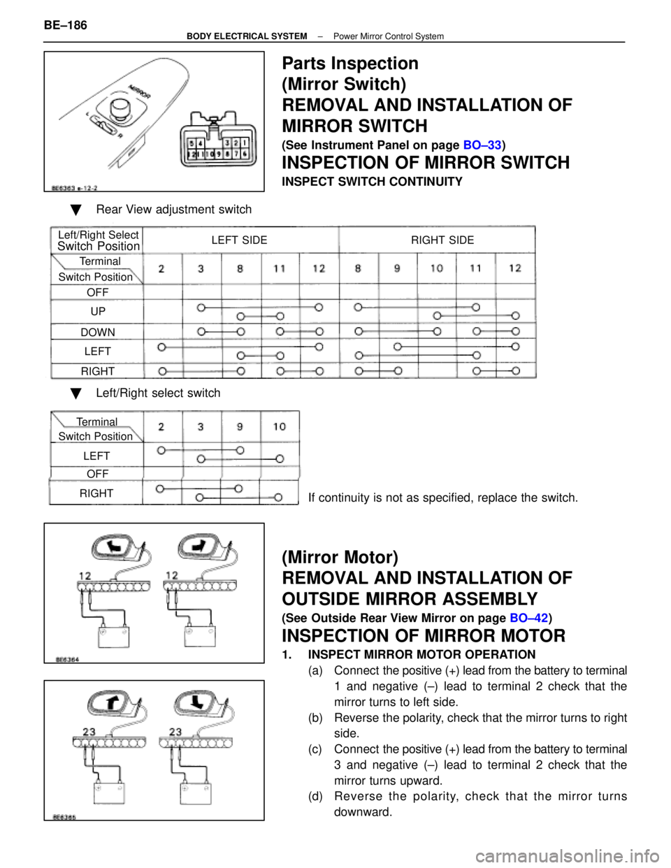
INSPECTION OF MIRROR SWITCH
INSPECT SWITCH CONTINUITY
� Rear View adjustment switch
Left/Right Select
Switch Position
Terminal
Switch Position OFF
UP
DOWN LEFT
RIGHT LEFT SIDE RIGHT SIDE
�
Left/Right select switch
If continuity is not as specified, replace the switch.
(Mirror Motor)
REMOVAL AND INSTALLATION OF
OUTSIDE MIRROR ASSEMBLY
(See Outside Rear View Mirror on page BO±42)
INSPECTION OF MIRROR MOTOR
1. INSPECT MIRROR MOTOR OPERATION
(a) Connect the positive (+) lead from the battery to terminal
1 and negative (±) lead to terminal 2 check that the
mirror turns to left side.
(b) Reverse the polarity, check that the mirror turns to right side.
(c) Connect the positive (+) lead from the battery to terminal
3 and negative (±) lead to terminal 2 check that the
mirror turns upward.
(d) Re ve rse th e po la rity, ch e ck th a t th e mirro r tu rn s
downward.
BE±186
±
BODY ELECTRICAL SYSTEM Power Mirror Control System
Terminal
Switch Position
OFF
LEFT
RIGHT
WhereEverybodyKnowsYourName
Page 578 of 4087

Parts Inspection
(Fuel Lid Opener Switch)
REMOVAL AND INSTALLATION OF FUEL
LID OPENER SWITCH
REMOVE AND INSTALL FUEL LID OPENER SWITCH(a) Remove No. 1 lower finish panel.
(See Instrument Panel on page BO±113)
(b) Remove the key cylinder, then remove the fuel lid opener
switch assembly from the pad.
(c) Install the opener switch assembly and key cylinder to
the pad.
(d) Install the No. 1 lower finish panel. (See Instrument Panel on page BO±116)
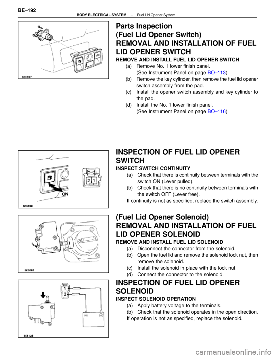
INSPECTION OF FUEL LID OPENER
SWITCH
INSPECT SWITCH CONTINUITY
(a) Check that there is continuity between terminals with the
switch ON (Lever pulled).
(b) Check that there is no continuity between terminals with
the switch OFF (Lever free).
If continuity is not as specified, replace the switch assembly.
(Fuel Lid Opener Solenoid)
REMOVAL AND INSTALLATION OF FUEL
LID OPENER SOLENOID
REMOVE AND INSTALL FUEL LID SOLENOID (a) Disconnect the connector from the solenoid.
(b) Open the fuel lid and remove the solenoid lock nut, thenremove the solenoid.
(c) Install the solenoid in place with the lock nut.
(d) Connect the connector to the solenoid.
INSPECTION OF FUEL LID OPENER
SOLENOID
INSPECT SOLENOID OPERATION (a) Apply battery voltage to the terminals.
(b) Check that the solenoid operates in the open direction.
If operation is not as specified, replace the solenoid.
BE±192
±
BODY ELECTRICAL SYSTEM Fuel Lid Opener System
WhereEverybodyKnowsYourName
Page 603 of 4087
ANTENNA CORD
ANTENNA CORD REMOVAL AND
INSTALLATION
1. REMOVE ANTENNA CORD
(a) Remove the following parts:wInstrument panel assembly
w Right front pillar garnish
w Roof headlining
w Roof side inner garnish
w Right center pillar garnish
w Right rear pillar garnish
w Package tray trim
w Room partition trim
w Luggage compartment RH cover
w Luggage compartment trim front cover
HINT: (See BO±section.)
(b) Remove antenna cord from motor antenna and glass printed antenna.
(c) Disconnect the connectors shown in the figure.
(d) Remove the clips and antenna cord assembly.
2. INSTALL ANTENNA CORD For installation follow the removal procedure in reverse.
±
BODY ELECTRICAL SYSTEM AUDIO SYSTEMBE±217
WhereEverybodyKnowsYourName