Page 8 of 4087
 Always replace cotter pins, gaskets, O±rings and oilseals etc. with new ones.
(b) Non±reusable parts are indicated in the component
illustrations by the º �º symbol.")
5. Non±reusable parts(a) Always replace cotter pins, gaskets, O±rings and oilseals etc. with new ones.
(b) Non±reusable parts are indicated in the component
illustrations by the º �º symbol.
6. Precoated parts Precoated parts are bolts and nuts, etc. that are coated with
a seal lock adhesive at the factory.
(a) If a precoated part is retightened, loosened or causedto move in any way, it must be recoated with the
specified adhesive.
(b) Recoating of precoated parts
(1) Clean off the old adhesive from the bolt, nut or threads.
(2) Dry with compressed air.
(3) Apply the specified seal lock adhesive to the bolt or nut threads.
(c) P re co a te d pa rts are in d ica te d in th e co m ponent
illustrations by the º �º symbol.
7. When necessary, use a sealer on gaskets to prevent leaks.
8. Carefully observe all specifications for bolt tightening
torques. Always use a torque wrench.
9. Use of special service tools (SST) and special service materials (SSM) may be required, depending on the nature
of the repair. Be sure to use SST and SSM where specified
and follow the proper work procedure. A list of SST and SSM
can be found in the preparation part at the front of each
section in this manual.
10. When replacing fuses, be sure the new fuse has the correct
amperage rating. DO NOT exceed the rating or use one with
a lower rating.
11. Care must be taken when jacking up and supporting the vehicle. Be sure to lift and support the vehicle at the proper
locations (See page IN±33).
(a) If the vehicle is to be jacked up only at the front or rear end, be sure to block the wheels at the opposite end in
order to ensure safety.
(b) After the vehicle is jacked up, be sure to support it on
stands. It is extremely dangerous to do any work on a
vehicle raised on a jack alone, even for a small job that
can be finished quickly.
±
INTRODUCTION General Repair InstructionsIN±5
WhereEverybodyKnowsYourName
Page 66 of 4087

INDICATOR
1. Turn the ignition switch on while pressing the ari conditioner control
switch and REC swich
simultaneously.
2. Check that all the indicators light up and go off at 1 second intervals 4 times in succession.
3. Check that the buzzer sounds when the indicators light up in 2.
HINT:
wAfter the indicator check is ended, the diagnostic code
check begins automatically.
w Press the OFF switch when desiring to cancel the check
mode.
DIAGNOSTIC CODE CHECK (SENSOR
CHECK)
1. Perform an indicator check. After the indicator check is completed, the system enters the diagnostic code check
mode automatically.
2. Read the code displayed on the panel. Refer to the list of
codes on page AC±28 when reading the codes. (Codes are
output at the temperature display.)
If the slower display ped is desired, press the FRS
switch and change it to stepped operation. Each time the
FRS
switch is pressed, the display changes by 1 step.
HINT:
w If the buzzer sounds when a code is being read, it means
the trouble indicated by that code continues to occur.
w If the buzzer does not sound when a code is being read,
it means the trouble indicated by that code occurred ear-
lier (such as poor connector contacts, etc.)
CLEARING DIAGNOSTIC CODES
1. Pull out the DOME fuse in Relay Block No. 2 for 10 sec. or
longer to clear the memory of diagnostic codes.
2. After reinserting the fuse, check that the normal code is output.
±
AIR CONDITIONING SYSTEM TroubleshootingAC±27
WhereEverybodyKnowsYourName
Page 109 of 4087
IG Power Source Circuit
CIRCUIT DESCRIPTION
This is the power source for the air conditioner control assembly (contains\
the A/C control assembly)
and servomotor, ect.
DIAGNOSTIC CHART
WIRING DIAGRAM
Check voltage between terminals IG+ and E
of air conditioner control assembly
connector.
Check continuity between terminal E of air
conditioner control assembly and
body ground.
Check HTR fuse.
Check harness and repair and connector be-
tween air conditioner control assembly and
battery
Proceed to next circuit inspection
shown on matrix chart (See page
AC-36).
Check for short in all the harness
and components connected to
the HTR fuse (See attached wir -
ing diagram).
Repair or replace harness or
connector.
AC±70±
AIR CONDITIONING SYSTEM Troubleshooting
WhereEverybodyKnowsYourName
Page 110 of 4087
 Remove console upper panel.(See pageBO-111 ).
(2) Remove A/C control assembly with connec±
tors still")
Check voltage between terminals IG+ and E of air conditioner control
assembly connector.
(1) Remove console upper panel.(See pageBO-111 ).
(2) Remove A/C control assembly with connec±
tors still connected.
(3) Turn ignition switch ON.
Measure voltage between terminals IG+ and E of air
conditioner control assembly.
Voltage: 10 ±14 V
Proceed to next circuit inspection shown on matrix
chart (See page AC-36).
Check continuity between terminals E of air conditioner control assem-
bly and body ground.
Measure resistance between terminals E of air condi-
tioner control assembly and body ground.
Resistance:�1 �� or less
Repair or replace harness or connector.
Remove HTR fuse from J/B No. 1.
Check continuity of HTR fuse
Continuity
Check HTR fuse.
Check for short in all the harness and
components connected to the HTR fuse
See attached wiring diagram).
Check and repair harness and connector between air conditioner control \
assembly and battery.
INSPECTION PROCEDURE
±
AIR CONDITIONING SYSTEM TroubleshootingAC±71
WhereEverybodyKnowsYourName
Page 111 of 4087
ACC Power Source Circuit
CIRCUIT DESCRIPTION
This circuit supplies power to the air conditioner control assembly (contai\
ns the A/C control assembly).
DIAGNOSTIC CHART
WIRING DIAGRAM
Check voltage between terminals ACC of air
conditioner control assembly connector
and body ground.
Check RADIO No. 2 fuse.
Check and repair harness and connector
between air conditioner control assembly
and battery.
Proceed to next circuit inspection
shown on matrix chart (See page
AC-36).
Check for short in all the harness
and components connected to
the RADIO No. 2 fuse (See
attached wiring diagram).
AC±72±
AIR CONDITIONING SYSTEM Troubleshooting
WhereEverybodyKnowsYourName
Page 112 of 4087
Check voltage between terminals ACC of air conditioner control
assembly connector and body ground.
(1) Remove console upper panel.(See page BO-111 ).
(2) Remove A/C control assembly with connec±
tors still connected.
(3) Turn ignition switch ON.
Measure voltage between terminals ACC of air
conditioner control assembly connector and body
ground.
Voltage: 10 ± 14 V
Proceed to next circuit inspection shown on matrix
chart (See page AC-36).
Check RADIO No. 2 fuse.
Remove RADIO No. 2 fuse from J/B No. 1.
Check continuity of RADIO No. 2 fuse.
Continuity.
Check for short in all the harness and
components connected to the RADIO No. 2
fuse (See attached wiring diagram).
Check and repair harness and connector between air conditioner control \
assembly and battery.
INSPECTION PROCEDURE
±
AIR CONDITIONING SYSTEM TroubleshootingAC±73
WhereEverybodyKnowsYourName
Page 113 of 4087
������������������\
������������������\
�
������������������\
�����������������
������������������\
������������������\
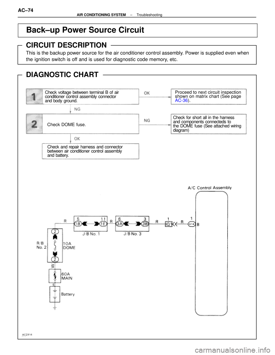
Back±up Power Source Circuit
CIRCUIT DESCRIPTION
This is the backup power source for the air conditioner control assembly. Power is supplied even when
the ignition switch is off and is used for diagnostic code memory, etc.
DIAGNOSTIC CHART
WIRING DIAGRAM
Check voltage between terminal B of air
conditioner control assembly connector
and body ground.
Check DOME fuse.
Proceed to next circuit inspection
shown on matrix chart (See page
AC-36
).
Check and repair harness and connector
between air conditioner control assembly
and battery.
Check for short all in the harness
and components connecteds to
the DOME fuse (See attached wiring
diagram)
AC±74±
AIR CONDITIONING SYSTEM Troubleshooting
WhereEverybodyKnowsYourName
Page 114 of 4087
Check voltage between terminals B of air conditioner control assembly
connector and body ground.
(1) Remove console upper panel.(See page BO-111 ).
(2) Remove A/C control assembly with connec±
tors still connected.
Measure voltage between terminals B of air condi-
tioner control assembly connector and body
ground.
Voltage: 10 ± 14 V
Proceed to next circuit inspection shown on matrix
chart (See page AC-36).
Check DOME fuse.
Remove DOME fuse from R/B No. 2.
Check continuity of DOME fuse.
Continuity.
Check for short in all the harness and
components connected to the DOME fuse
(See attached wiring diagram).
Check and repair harness and connector between air conditioner control \
assembly and battery.
INSPECTION PROCEDURE
±
AIR CONDITIONING SYSTEM TroubleshootingAC±75
WhereEverybodyKnowsYourName

and servomotor, ect.
DIAGNOSTIC CHART
WIRING DIAGRA")
.
DIAGNOSTIC CHART
WIRING DIAGRAM
Check voltage b")
 Remove console upper panel.(See page BO-111 ).
(2) Remove A/C control assembly with connec±
t")
 Remove console upper panel.(See page BO-111 ).
(2) Remove A/C control assembly with connec±
tors")