Page 620 of 4087
11Tape playerCASSETTE TAPE CANNOT BE INSERTED
A. without CD player type
Wire harness faulty. Radio receiver assembly faulty.
Is there continuity between the following terminals
with connector connected?
� Radio receiver amplifier A3 ± ground
� Radio receiver amplifier A4 ± ground
Radio receiver assembly faulty.
Is there continuity between the following terminals
with connector disconnected?
�
Radio receiver assembly A7 ± ground Replace fuse.
Wire harness faulty.Remove foreign object.
Is there a foreign object inside tape player?
Is radio operating normally?
Check if RADIO No. 1 and RADIO No. 2 fuses
are OK.
BE±234±
BODY ELECTRICAL SYSTEM AUDIO SYSTEM
WhereEverybodyKnowsYourName
Page 621 of 4087
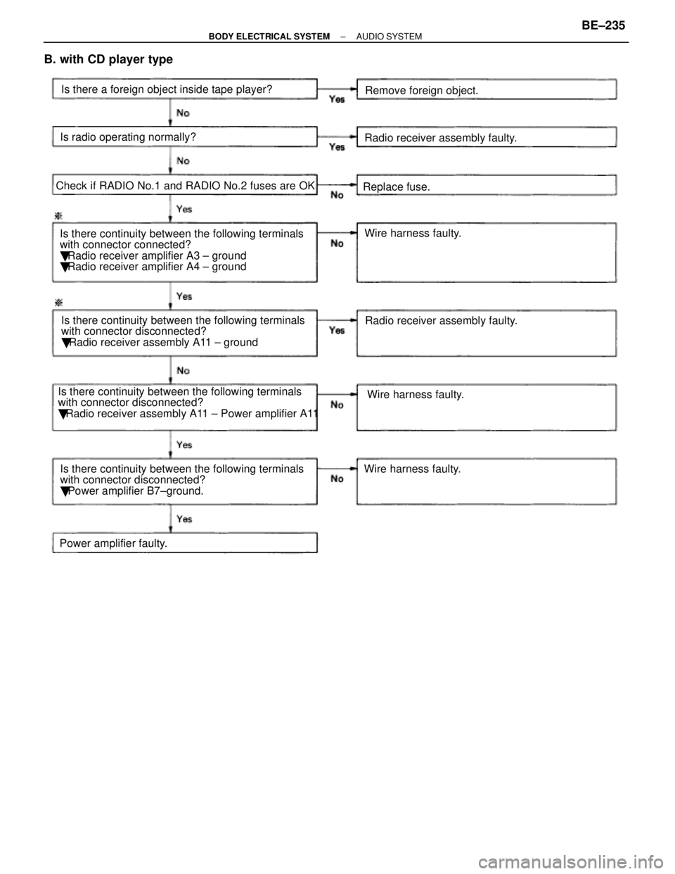
B. with CD player type
Wire harness faulty. Radio receiver assembly faulty.
Is there continuity between the following terminals
with connector connected?
� Radio receiver amplifier A3 ± ground
� Radio receiver amplifier A4 ± ground
Power amplifier faulty. Is there continuity between the following terminals
with connector disconnected?
�
Radio receiver assembly A11 ± ground Replace fuse.
Wire harness faulty.
Remove foreign object.
Is there a foreign object inside tape player?
Is radio operating normally?
Check if RADIO No.1 and RADIO No.2 fuses are OK
Wire harness faulty.Radio receiver assembly faulty.
Is there continuity between the following terminals
with connector disconnected?
� Radio receiver assembly A11 ± Power amplifier A11
Is there continuity between the following terminals
with connector disconnected?
� Power amplifier B7±ground.
±
BODY ELECTRICAL SYSTEM AUDIO SYSTEMBE±235
WhereEverybodyKnowsYourName
Page 622 of 4087
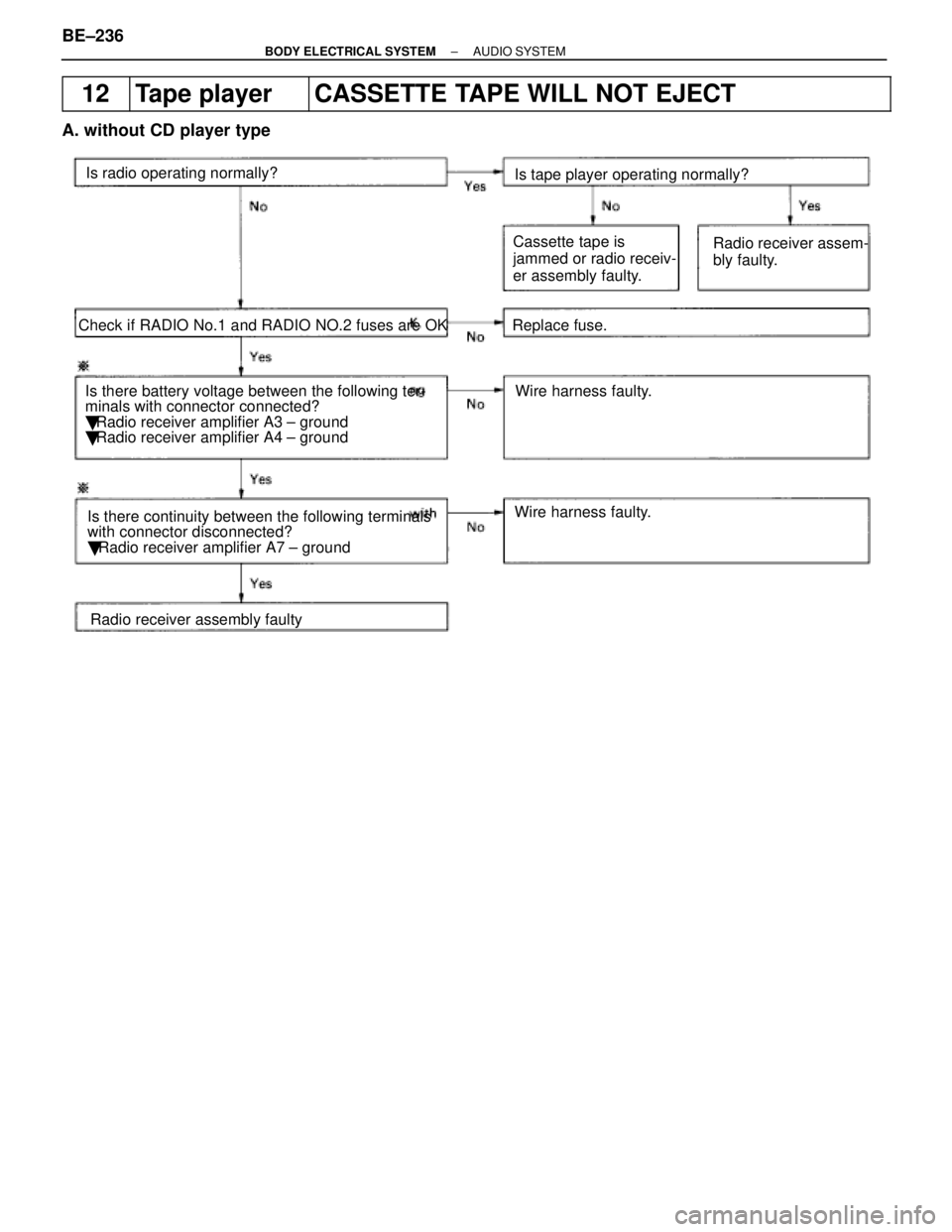
12Tape playerCASSETTE TAPE WILL NOT EJECT
A. without CD player type
Is there battery voltage between the following ter-
minals with connector connected?
� Radio receiver amplifier A3 ± ground
� Radio receiver amplifier A4 ± ground Replace fuse.
Wire harness faulty.
Wire harness faulty.
Is radio operating normally?
Check if RADIO No.1 and RADIO NO.2 fuses are OK Is tape player operating normally?
Radio receiver assembly faulty
Is there continuity between the following terminals
with connector disconnected?
�
Radio receiver amplifier A7 ± ground Cassette tape is
jammed or radio receiv-
er assembly faulty.
Radio receiver assem-
bly faulty.
BE±236±
BODY ELECTRICAL SYSTEM AUDIO SYSTEM
WhereEverybodyKnowsYourName
Page 623 of 4087
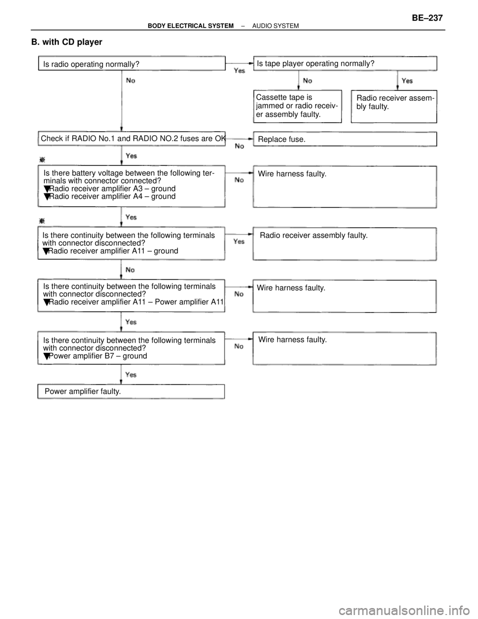
B. with CD player
Is there battery voltage between the following ter-
minals with connector connected?
� Radio receiver amplifier A3 ± ground
� Radio receiver amplifier A4 ± ground Replace fuse.
Wire harness faulty.
Is radio operating normally?
Check if RADIO No.1 and RADIO NO.2 fuses are OK Is tape player operating normally?
Power amplifier faulty.
Is there continuity between the following terminals
with connector disconnected?
�
Radio receiver amplifier A11 ± ground Cassette tape is
jammed or radio receiv-
er assembly faulty.
Radio receiver assem-
bly faulty.
Wire harness faulty. Wire harness faulty.Radio receiver assembly faulty.
Is there continuity between the following terminals
with connector disconnected?
� Radio receiver amplifier A11 ± Power amplifier A11
Is there continuity between the following terminals
with connector disconnected?
� Power amplifier B7 ± ground
±
BODY ELECTRICAL SYSTEM AUDIO SYSTEMBE±237
WhereEverybodyKnowsYourName
Page 646 of 4087

32AntennaANTENNA±RELATED
Does antenna extend when radio switched ON?Wire harness faulty.
Is there battery voltage between the following
terminals with connector disconnected?
�
Motor antenna control relay 6 ± ground
� Motor antenna control relay 14 ± ground
� Motor antenna control relay 3 ± ground
Wire harness faulty.Replace fuses.
Radio receiver assembly faulty.
Check if ECU±IG, RADIO No. 1 and RADIO No.
2 fuse are OK.
ªAMº button turned ON.
Is there battery voltage between the following
terminals with connector connected?
� Radio receiver assembly A9 (*A1) ± ground
� Radio receiver assembly A8 ± ground
� Radio receiver assembly D4 ± ground
� Radio receiver assembly D10 ± ground Radio receiver side
faulty.
Motor antenna faulty.
Temporarily install another motor antenna is
radio operating normally?
Glass printed antenna faulty.
Check if glass printed antenna is OK.
Is there continuity between the following terminals
with connector disconnected?
� Motor antenna control relay 4 ± ground
Continued on next page.
BE±260±
BODY ELECTRICAL SYSTEM AUDIO SYSTEM
WhereEverybodyKnowsYourName
Page 650 of 4087

HORN RELAY
HORN RELAY INSPECTION
INSPECT RELAY CONTINUITY AND OPERATION
If operation is not as specified, replace the relay.
Troubleshooting
You will find the cause of trouble more easily by properly using the tabl\
e shown below. In this table, the
numbers indicate the order of priority of the causes of trouble. Check each part in \
the order shown. If neces-
sary, replace these part.
See page
BE±4 , 21BE±264BE±263BE±263
±
Trouble
Parts
name
HAZ±HORN FuseHorn SwitchHorn SwitchHornWire Harness
������������������\
������������������\
Horn system does not operate����� �����1���� ����2����� �����3���� ����4����� �����5������������������\
�
�����������������
������������������\
Horns blow all the time
����� �
����
�����
���� �
���
����1
����� �
����
�����2
���� �
���
����
����� �
����
�����3
������������������\
�
�����������������
������������������\
One horn operates but other horn does not
Operate����� �
����
�����
���� �
���
����
����� �
����
�����
���� �
���
����
1����� �
����
�����
2
������������������\
������������������\
Horns operate abnormally����� ��������� ����1����� ��������� ����2����� �����3
BE±264±
BODY ELECTRICAL SYSTEM HORN SYSTEM
WhereEverybodyKnowsYourName
Page 652 of 4087

DESCRIPTION
The Power Seat Control System carries out seat slide, front vertical, rear \
vertical, reclining and lumbar support
position adjustments electrically. Power seat switch and lumbar support switch.
In addition, operation of the memory switch makes it possible to store the positions of the slide, front vertical,
rear vertical and reclining adjustments in memory and return to the posi\
tion.
The component parts of this system and their function are described in t\
he following table.
������� �������Parts Name������������������\
������������ ������������������\
������������Function
������� �
������
�
������
�
������
�
������
�������
Driver's Seat ECU
������������������\
������������ �
������������������\
�����������
�
������������������\
�����������
�
������������������\
�����������
�
������������������\
�����������
������������������\
������������
The seat ECU controls power operation, memory operation, and position re\
turn
operation of the power seat. When input is received from the power seat \
switch,
the relay inside the ECU is controlled and the power seat operates. The \
seat
memory and position return are controlled by mutual communication betwee\
n the
electrically operated Tilt and Telescopic ECU and the seat ECU.
������� �
������
�������Power Seat Switch������������������\
������������ �
������������������\
�����������
������������������\
������������
Operation of this switch sends slide, front vertical, rear vertical, rec\
lining signals
to ECU.
������� �
������
�
������
�������
Driving Position
Memory and Return
Switch������������������\
������������ �
������������������\
�����������
�
������������������\
�����������
������������������\
������������
Memory and Return Signals are sent to the seat ECU via the Tilt and Telescopic
ECU.
������� �
������
�
������
�
������
�������
Lumbar Support
Switch
������������������\
������������ �
������������������\
�����������
�
������������������\
�����������
�
������������������\
�����������
������������������\
������������
This switch is supplied with power from the DOOR fuse. When the switch i\
s
operated, power is supplied to the lumbar support motor controlling the \
direction
in which the motor turns and turning the current ON and OFF. This switch is not
connected to the ECU and the adjustment position cannot be stored in mem\
ory
for return operation.
������� �
������
�������Position Sensor
������������������\
������������ �
������������������\
�����������
������������������\
������������This sensor sends signals on the position of each motor (slide, front v\
ertical, rear
vertical and reclining) to the ECU for use in memory and return.
������� �
������
�������*Motor
������������������\
������������ �
������������������\
�����������
������������������\
������������
These motors operate on current from the driver's seat ECU moving the various
parts of the seat directly. Each motor has a built±in circuit breaker.
*: Slide, Front Vertical, Rear Vertical, Lumbar Support and Reclining.
Motors contained in each seat are described in the following table.
������ ������Motor������ ������Slide����� �����Front
Vertical
����� �����Rear
Vertical
������ ������Reclining������ ������Lumbar
Support������ �
�����
������Seat������ �
�����
������Motor����� �
����
�����
Vertical
Motor
����� �
����
�����
Vertical
Motor
������ �
�����
������
g
Motor������ �
�����
������
Support
Motor
������ ������Driver's Seat������ ������O*����� �����O*����� �����O*������ ������O*������ ������O
*: Operated by the memory and return functions. BE±266
±
BODY ELECTRICAL SYSTEM Power Seat Control System (Driver's Seat)
WhereEverybodyKnowsYourName
Page 668 of 4087
CIRCUIT INSPECTION
+B Power Source Circuit
CIRCUIT DESCRIPTION
This is the power source for motors such as the slide motor and reclining mo\
tor.
DIAGNOSTIC CHARTDIAGNOSTIC CHART
Check Door fuse.NG
Check for short in all harness and
components connected to the
DOOR fuse (See attached wiring
diagram).
Check voltage between terminals +B, +B2
and GND of ECU connector. OK
OKProceed to next circuit inspection
shown on matrix chart (See page
BE±276
).
Check continuity between terminal GND
of ECU connector and body ground. NG
NGRepair or replace harness or
connector.
OK
Check and repair harness or connector
between ECU and battery.
WIRING DIAGRAM
BE±284±
BODY ELECTRICAL SYSTEM Power Seat Control System (Driver's Seat)
WhereEverybodyKnowsYourName