Page 562 of 4087

SLIDING ROOF SYSTEM
Description
Standby Operation
� Current flows from the DOME fuse to terminal A1 of the sliding roof control rel\
ay (hereafter called
relay).
� When the ignition switch is ON, the current flows from the power window relay to terminal A3 of the
relay.
Operation
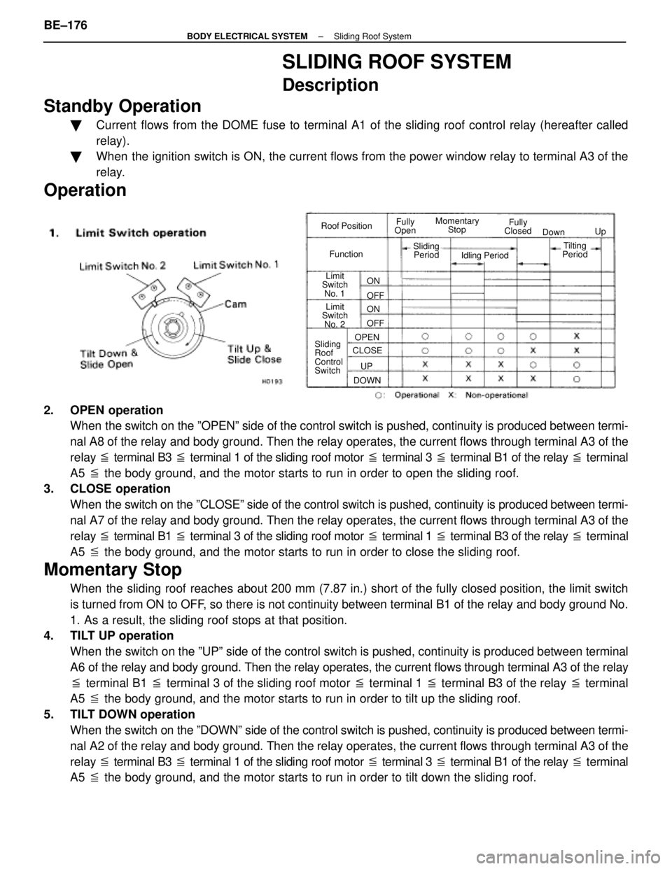
Roof Position
Function Fully
Open Fully
Closed
Momentary
Stop
Limit
Switch
No. 1
Limit
Switch
No. 2
Sliding
Roof
Control
Switch Down
Up
Sliding Period Idling Period
CLOSE DOWN OPEN
UP ON
ON OFF
OFF
Tilting
Period
2. OPEN operation
When the switch on the ºOPENº side of the control switch is pushed, co\
ntinuity is produced between termi-
nal A8 of the relay and body ground. Then the relay operates, the curren\
t flows through terminal A3 of the
relay � terminal B3 � terminal 1 of the sliding roof motor � terminal 3 � terminal B1 of the relay � terminal
A5 � the body ground, and the motor starts to run in order to open the slidi\
ng roof.
3. CLOSE operation
When the switch on the ºCLOSEº side of the control switch is pushed, c\
ontinuity is produced between termi-
nal A7 of the relay and body ground. Then the relay operates, the current f\
lows through terminal A3 of the
relay � terminal B1 � terminal 3 of the sliding roof motor � terminal 1 � terminal B3 of the relay � terminal
A5 � the body ground, and the motor starts to run in order to close the slid\
ing roof.
Momentary Stop
When the sliding roof reaches about 200 mm (7.87 in.) short of the fully closed position, the limit \
switch
is turned from ON to OFF, so there is not continuity between terminal B1 of the relay and body g\
round No.
1. As a result, the sliding roof stops at that position.
4. TILT UP operation
When the switch on the ºUPº side of the control switch is pushed, cont\
inuity is produced between terminal
A6 of the relay and body ground. Then the relay operates, the current flow\
s through terminal A3 of the relay
� terminal B1 � terminal 3 of the sliding roof motor � terminal 1 � terminal B3 of the relay � terminal
A5 � the body ground, and the motor starts to run in order to tilt up the sl\
iding roof.
5. TILT DOWN operation When the switch on the ºDOWNº side of the control switch is pushed, co\
ntinuity is produced between termi-
nal A2 of the relay and body ground. Then the relay operates, the current f\
lows through terminal A3 of the
relay � terminal B3 � terminal 1 of the sliding roof motor � terminal 3 � terminal B1 of the relay � terminal
A5 � the body ground, and the motor starts to run in order to tilt down the \
sliding roof.
BE±176
±
BODY ELECTRICAL SYSTEM Sliding Roof System
WhereEverybodyKnowsYourName
Page 568 of 4087

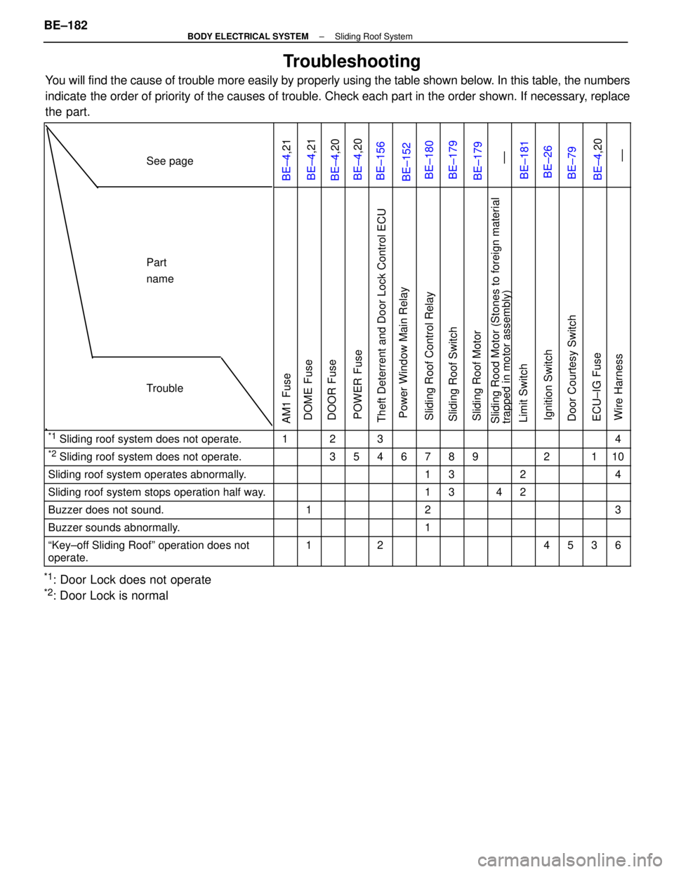
Troubleshooting
You will find the cause of trouble more easily by properly using the tabl\
e shown below. In this table, the numbers
indicate the order of priority of the causes of trouble. Check each part in the \
order shown. If necessary, replace
the part.
See page
BE±4,21BE±4,21BE±4,20BE±4,20BE±156BE±152BE±180BE±179BE±179 ±±BE±181BE±26BE±79BE±4,20 ±±
Part
name
Trouble
AM1 FuseDOME FuseDOOR FusePOWER FuseTheft Deterrent and Door Lock Control ECUPower Window Main RelaySliding Roof Control RelaySliding Roof SwitchSliding Roof MotorSliding Rood Motor (Stones to foreign material
trapped in motor assembly)Limit SwitchIgnition SwitchDoor Courtesy SwitchECU±IG FuseWire Harness
*1 Sliding roof system does not operate.1234
*2 Sliding roof system does not operate.35467892110
Sliding roof system operates abnormally.1324
Sliding roof system stops operation half way.1342
Buzzer does not sound.123
Buzzer sounds abnormally.1
ªKey±off Sliding Roofº operation does not
operate.124536
*1: Door Lock does not operate
*2: Door Lock is normal
BE±182
±
BODY ELECTRICAL SYSTEM Sliding Roof System
WhereEverybodyKnowsYourName
Page 569 of 4087

POWER MIRROR CONTROL
SYSTEM
Description
The Power Miror Control System carries out mirror left/right and up/down ad\
justments electrically when the Mir-
ror Switch is operated. In addition, operation of the Driving Position M\
emory and Return Switches makes it pos-
sible to store the adjusted position in memory and reproduce each adjustment \
when desired. The component
parts of this system and their functions are described in the following table\
.
Parts NameFunction
Outside Rear View
Mirror ECUThe Outside Rear View Mirror ECU is supplied with power from the DOME and RADIO
NO.2 fuses and is connected to the Tilt and Telescopic ECU, Mirror Switch, each
mirror motor and ground.
Rear View Adjustment
SwitchOperation of this switch sends left/right, up/down signals to Outside Re\
ar View Mirror
ECU.
Driving Position Memory
and Return SwitchesMemory and return signals are sent to the ECU via the Tilt and Telescopic ECU.
Mirror MotorThese motors operate on current from the Outside Rear View Mirror ECU, moving
the various parts of the mirror directly.
These sensors send signals about the motor positions to the ECU for stor\
ing in memory
and during return operation.
Left/Right Select SwitchThis switch is used to select operation of the Rear View Adjustment Switch for the
leftor right hand side mirror.
±
BODY ELECTRICAL SYSTEM Power Mirror Control SystemBE±183
WhereEverybodyKnowsYourName
Page 576 of 4087
Troubleshooting
You will find the cause of trouble more easily by properly using the table \
shown below. In this table, the
numbers indicate the order of priority of the causes of trouble. Check each part in \
the order shown. If neces-
sary, replace the part.
See pageBE±4 ,20BE±4,21BE±186BE±186 ±±BE±188SR±60 ±±IN±32BE±187
TroubleParts
name
RADIO NO. 2 FuseDOME FuseMirror SwitchMirror MotorWire HarnessMirror ECUDriving Position SwitchDriving Position Switch
(Position is not set)Tilt and Telescopic ECUMirror Sensors
Mirror does not operate.112354
Mirror operates abnormally1243
Mirror does not return to the memorized position.
(w/ Memory System)642135
Mirror returns to a position which is not memorized.
(w/ Memory System)312
BE±190±
BODY ELECTRICAL SYSTEM Power Mirror Control System
WhereEverybodyKnowsYourName
Page 579 of 4087
Troubleshooting
You will find the cause of trouble more easily by properly using the tabl\
e shown below. In this table, the numbers
indicate the order or priority of the causes of trouble. Check each part\
in the order shown. If necessary, replace
the part.
See page
BE ± 4, 20BE ± 192BE ± 192
±
Trouble
Part Name
DOOR FuseFuel Lid Opener Switch
Mirror SwitchFuel Lid Opener SolenoidWire Harness
Fuel lid opener system does not operate1234
±
BODY ELECTRICAL SYSTEM Fuel Lid Opener SystemBE±193
WhereEverybodyKnowsYourName
Page 580 of 4087
CLOCK
Troubleshooting
HINT: Troubleshoot the clock according to the table below.
Clock will not operate1
Clock loses or gains time2
1CLOCK WILL NOT OPERATE
(a) Check that the battery voltage is 10±16 V.
If voltage is not as specified, replace the battery.
(b) Check that the DOME fuse is not blown.
If the fuse is blown, replace the fuse and check for short.
(c) Troubleshoot the clock as follows.
HINT: Inspect the connector on the wire harness side.
BE±194
±
BODY ELECTRICAL SYSTEM Clock
Is there battery voltage between terminal
+B and body ground?
Is there continuity between terminal GND
and body ground?
Replace clock. Open or
short circuit in wire harness between
terminal +B and DOME fuse.
Open circuit in wire harness between
terminal GND and body ground.
WhereEverybodyKnowsYourName
Page 606 of 4087

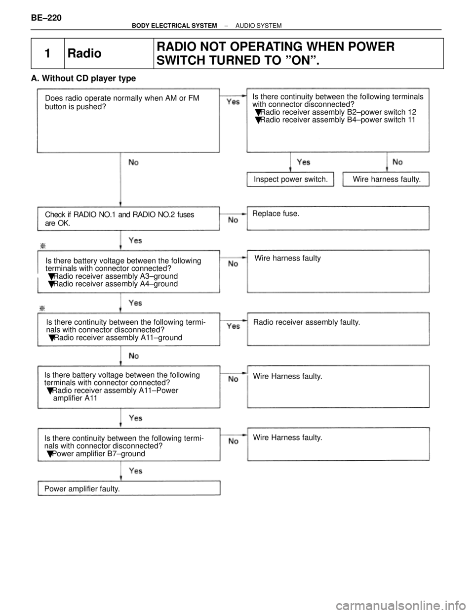
1RadioRADIO NOT OPERATING WHEN POWER
SWITCH TURNED TO ºONº.
A. Without CD player type
Does radio operate normally when AM or FM
button is pushed?
Check if RADIO NO.1 and RADIO NO.2 fuses
are OK.Is there battery voltage between the following
terminals with connector connected?
� Radio receiver assembly A3±ground
� Radio receiver assembly A4±ground
Is there continuity between the following termi-
nals with connector disconnected?
� Radio receiver assembly A11±ground Radio receiver assembly faulty.Wire harness faulty
Wire Harness faulty.
Replace fuse.
Inspect power switch. Wire harness faulty.
Is there continuity between the following terminals
with connector disconnected?
� Radio receiver assembly B2±power switch 12
� Radio receiver assembly B4±power switch 11
Wire Harness faulty.
Is there battery voltage between the following
terminals with connector connected?
� Radio receiver assembly A11±Power
amplifier A11
Is there continuity between the following termi-
nals with connector disconnected?
� Power amplifier B7±ground
Power amplifier faulty.
BE±220±
BODY ELECTRICAL SYSTEM AUDIO SYSTEM
WhereEverybodyKnowsYourName
Page 607 of 4087

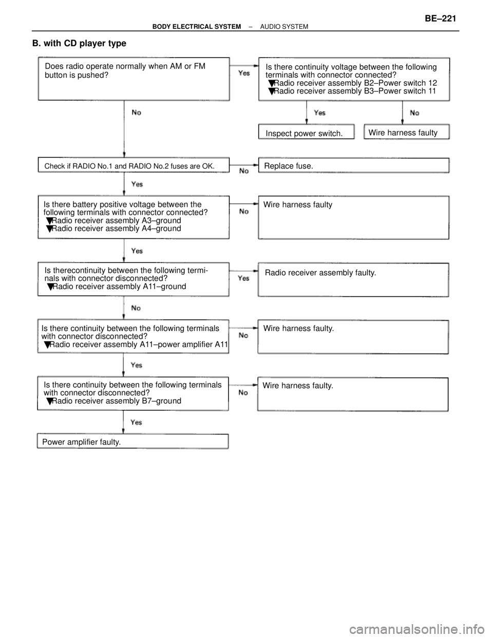
B. with CD player type
Does radio operate normally when AM or FM
button is pushed?
Is there battery positive voltage between the
following terminals with connector connected?
� Radio receiver assembly A3±ground
� Radio receiver assembly A4±ground
Check if RADIO No.1 and RADIO No.2 fuses are OK.
Is therecontinuity between the following termi-
nals with connector disconnected?
� Radio receiver assembly A11±ground Replace fuse.
Wire harness faulty
Radio receiver assembly faulty.
Wire harness faulty.
Wire harness faulty. Inspect power switch.
Wire harness faulty
Is there continuity voltage between the following
terminals with connector connected?
� Radio receiver assembly B2±Power switch 12
� Radio receiver assembly B3±Power switch 11
Is there continuity between the following terminals
with connector disconnected?
� Radio receiver assembly A11±power amplifier A11
Is there continuity between the following terminals
with connector disconnected?
� Radio receiver assembly B7±ground
Power amplifier faulty.
±
BODY ELECTRICAL SYSTEM AUDIO SYSTEMBE±221
WhereEverybodyKnowsYourName