Page 708 of 4087
OKNG
NGOK
OKNG
INSPECTION PROCEDURE
1Check DOOR fuse.
Check for short in all the harness components con-
nected to the DOOR fuse and repair them (See attached
wiring diagram). *1
2Check voltage between terminals +B and GND of ECU connector.
C
OK
PRemove passenger's seat ECU with connectors still
connected.
Measure voltage between terminals +B and GND of
ECU connector.
Voltage: 10 ± 14 V
Proceed to next circuit inspection shown on matrix chart
(See page BE±319).
3Check continuity between terminal GND of ECU connector and body ground.
C
OK
Measure resistance between terminal GND of ECU and
body ground.
Resistance: 1 � or less
Repair or replace harness or connector.
Check and repair harness or connector between
ECU and battery.
±
BODY ELECTRICAL SYSTEM Power Seat Control System (Passenger's Seat)BE±327
WhereEverybodyKnowsYourName
Page 715 of 4087
Slide Switch Circuit
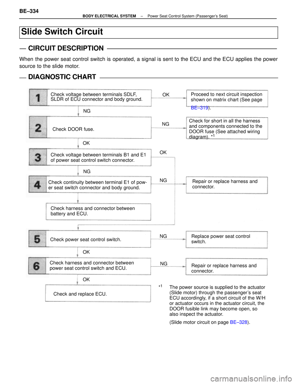
CIRCUIT DESCRIPTION
When the power seat control switch is operated, a signal is sent to the ECU and the ECU applies the power
source to the slide motor.
DIAGNOSTIC CHARTDIAGNOSTIC CHART
Check voltage between terminals SDLF,
SLDR of ECU connector and body ground.OK
NG
OK OK
OK
OK NG
NG NG
NG
NG Proceed to next circuit inspection
shown on matrix chart (See page
BE±319
).
Check DOOR fuse. Check for short in all the harness
and components connected to the
DOOR fuse (See attached wiring
diagram). *
1
Check voltage between terminals B1 and E1
of power seat control switch connector.
Check continuity between terminal E1 of pow-
er seat switch connector and body ground. Repair or replace harness and
connector.
Check harness and connector between
battery and ECU.
Check power seat control switch. Replace power seat control
switch.
Check harness and connector between
power seat control switch and ECU. Repair or replace harness and
connector.
Check and replace ECU. *
1The power source is supplied to the actuator
(Slide motor) through the passenger's seat
ECU accordingly, if a short circuit of the W/H
or actuator occurs in the actuator circuit, the
DOOR fusible link may become open, so
also inspect the actuator.
(Slide motor circuit on page
BE±328).
BE±334±
BODY ELECTRICAL SYSTEM Power Seat Control System (Passenger's Seat)
WhereEverybodyKnowsYourName
Page 716 of 4087
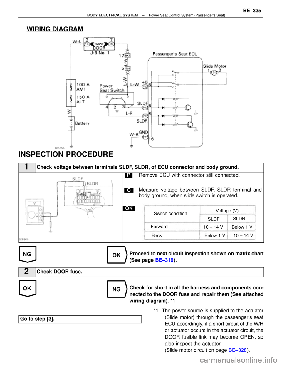
WIRING DIAGRAM
NGOK
*1 The power source is supplied to the actuator(Slide motor) through the passenger's seat
ECU accordingly, if a short circuit of the W/H
or actuator occurs in the actuator circuit, the
DOOR fusible link may become OPEN, so
also inspect the actuator.
(Slide motor circuit on page BE±328).
OKNG
INSPECTION PROCEDURE
1Check voltage between terminals SLDF, SLDR, of ECU connector and body ground.
C
OK
PRemove ECU with connector still connected.
Measure voltage between SLDF, SLDR terminal and
body ground, when slide switch is operated.
Switch condition Voltage (V)
SLDF SLDR
Forward
Back 10 ± 14 V Below 1 V
Below 1 V 10 ± 14 V
Proceed to next circuit inspection shown on matrix chart
(See page BE±319).
2Check DOOR fuse.
Check for short in all the harness and components con-
nected to the DOOR fuse and repair them (See attached
wiring diagram). *1
Go to step [3].
±
BODY ELECTRICAL SYSTEM Power Seat Control System (Passenger's Seat)BE±335
WhereEverybodyKnowsYourName
Page 743 of 4087
Check DOME fuse.NG OKCheck for short in all the harness
and components connected to the
DOME fuse (See attached wiring
diagram).1
Check and repair harness and connector
between ECU and battery. Proceed to next circuit inspection
shown on matrix chart (See page
BE±371
).
Repair or replace harness or
connector.
Check voltage between terminals +B1
and E of ECU connector.
Check for open in harness and connector
between ECU and body ground (See page
IN±27 ).
OK
OK
NG
NG
2
3
WIRING DIAGRAM
CIRCUIT INSPECTION
ECU Power Source Circuit
CIRCUIT DESCRIPTION
This circuit provides power to operate the theft deterrent and door lock ECU\
.
DIAGNOSTIC CHART
BE±376±
BODY ELECTRICAL SYSTEM Door Lock Control System
WhereEverybodyKnowsYourName
Page 744 of 4087
OKNG
NGOK
OKNG
INSPECTION PROCEDURE
1Check DOME fuse.
C
OK
PRemove DOME fuse from R/B No. 2.
Check continuity of DOME fuse.
Continuity
Check for short in all the harness and components con-
nected to the DOME fuse (See attached wiring diagram).
2Check voltage between terminals +B1 and E of ECU connector.
C
OK
P1. Remove the No. 1 under cover and heater duct.
2. Disconnect the theft deterrent and door lock ECUconnectors.
Measure voltage between terminals +B1 and E of ECU
connector.
Voltage: 10 ± 14 V
Proceed to next circuit inspection shown on matrix chart
(See page BE±371).
3Check for open in harness and connector between ECU and body ground (Se\
e page IN±27).
Repair or replace harness or connector.
Check and repair harness and connector between
ECU and battery.
±
BODY ELECTRICAL SYSTEM Door Lock Control SystemBE±377
WhereEverybodyKnowsYourName
Page 745 of 4087
NGOK
NG
OK
1
2
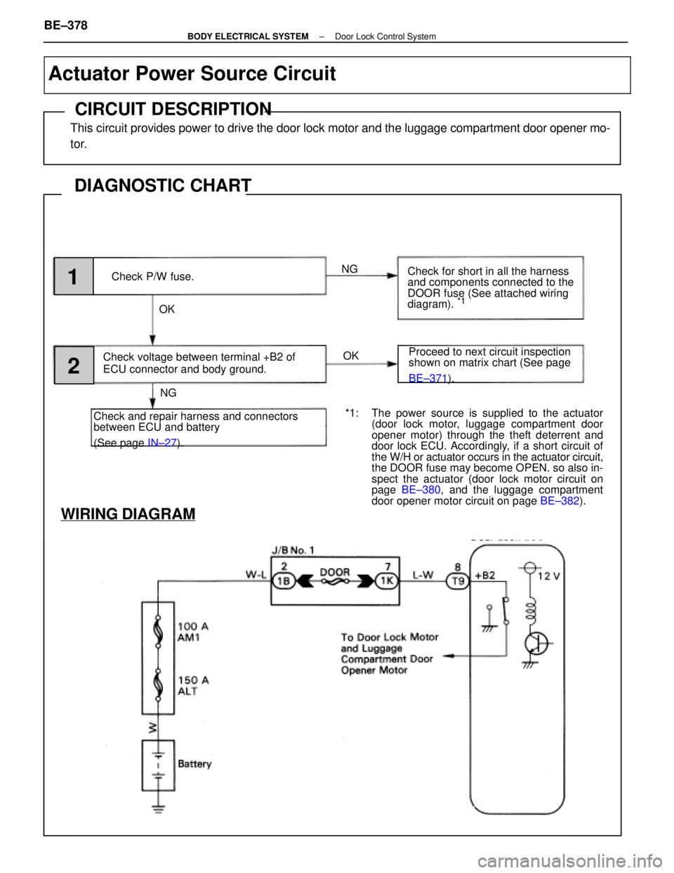
Check P/W fuse.
Check voltage between terminal +B2 of
ECU connector and body ground.
Check and repair harness and connectors
between ECU and battery
(See page IN±27). Check for short in all the harness
and components connected to the
DOOR fuse (See attached wiring
diagram).
*1
Proceed to next circuit inspection
shown on matrix chart (See page
BE±371
).
WIRING DIAGRAM
*1: The power source is supplied to the actuator
(door lock motor, luggage compartment door
opener motor) through the theft deterrent and
door lock ECU. Accordingly, if a short circuit of
the W/H or actuator occurs in the actuator circuit,
the DOOR fuse may become OPEN. so also in-
spect the actuator (door lock motor circuit on
page BE±380 , and the luggage compartment
door opener motor circuit on page BE±382).
Actuator Power Source Circuit
CIRCUIT DESCRIPTION
This circuit provides power to drive the door lock motor and the luggage com\
partment door opener mo-
tor.
DIAGNOSTIC CHART
BE±378±
BODY ELECTRICAL SYSTEM Door Lock Control System
WhereEverybodyKnowsYourName
Page 746 of 4087
OKNG
NGOK
*1: The power source is supplied to the actuator (doorlock motor, luggage compartment door opener mo-
tor) through the theft deterrent and door lock ECU.
Accordingly, if a short circuit of the W/H or actuator
occurs in the actuator circuit, the DOOR fusible link
may become OPEN, so also inspect the actuator
(door lock motor circuit on page BE±380, and the
luggage compartment door opener motor circuit on
page BE±382 ).
INSPECTION PROCEDURE
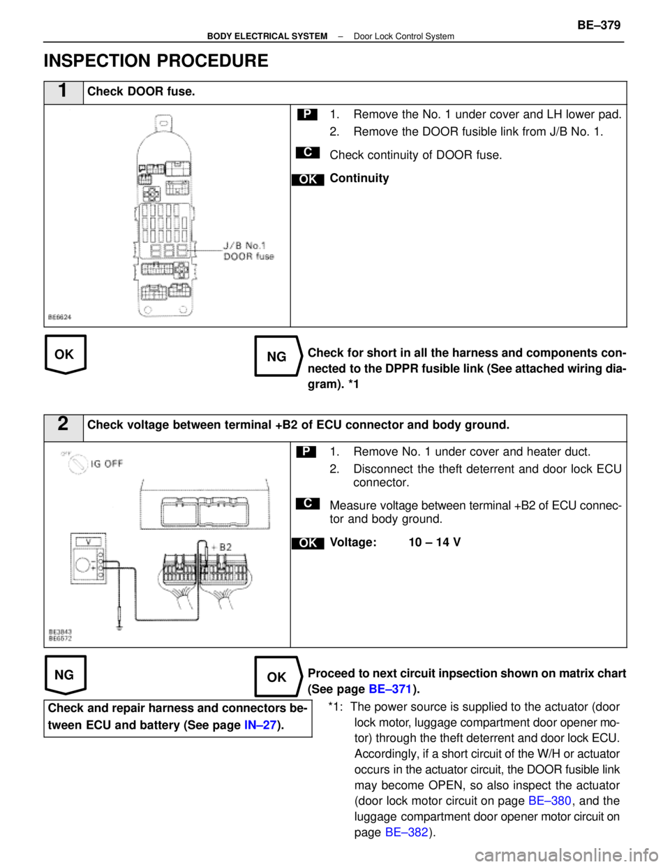
1Check DOOR fuse.
C
OK
P1. Remove the No. 1 under cover and LH lower pad.
2. Remove the DOOR fusible link from J/B No. 1.
Check continuity of DOOR fuse.
Continuity
Check for short in all the harness and components con-
nected to the DPPR fusible link (See attached wiring dia-
gram). *1
2Check voltage between terminal +B2 of ECU connector and body ground.
C
OK
P1. Remove No. 1 under cover and heater duct.
2. Disconnect the theft deterrent and door lock ECU connector.
Measure voltage between terminal +B2 of ECU connec-
tor and body ground.
Voltage: 10 ± 14 V
Proceed to next circuit inpsection shown on matrix chart
(See page BE±371).
Check and repair harness and connectors be-
tween ECU and battery (See page IN±27).
±
BODY ELECTRICAL SYSTEM Door Lock Control SystemBE±379
WhereEverybodyKnowsYourName
Page 784 of 4087
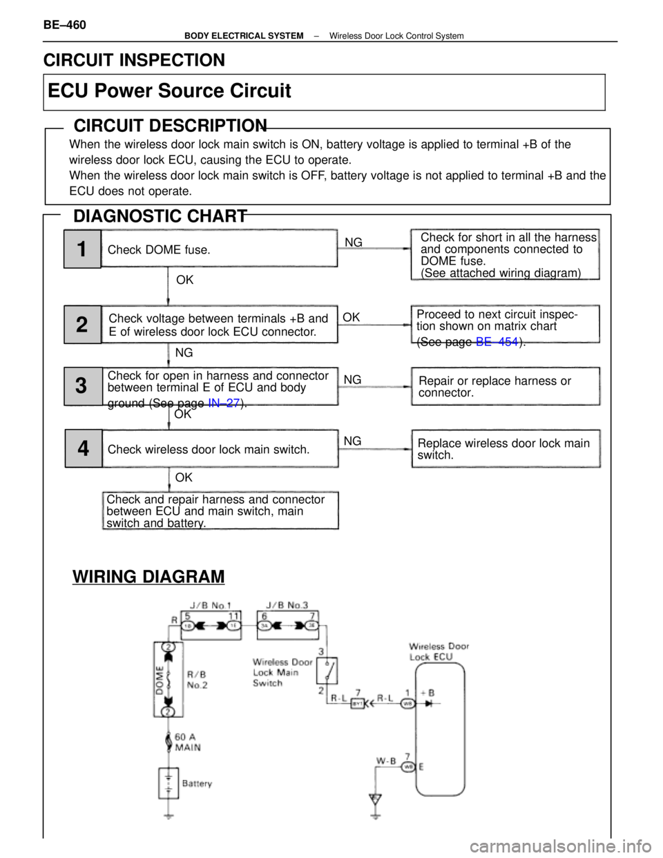
WIRING DIAGRAM
Check DOME fuse.NG
OK Check for short in all the harness
and components connected to
DOME fuse.
(See attached wiring diagram)
Check voltage between terminals +B and
E of wireless door lock ECU connector.
Check for open in harness and connector
between terminal E of ECU and body
ground (See page IN±27).
Check and repair harness and connector
between ECU and main switch, main
switch and battery. Check wireless door lock main switch. Proceed to next circuit inspec-
tion shown on matrix chart
(See page
BE±454).
Repair or replace harness or
connector.
Replace wireless door lock main
switch.
NG
NG
NG
OK
OK OK1
2
3
4
CIRCUIT INSPECTION
ECU Power Source Circuit
CIRCUIT DESCRIPTION
When the wireless door lock main switch is ON, battery voltage is applied to\
terminal +B of the
wireless door lock ECU, causing the ECU to operate.
When the wireless door lock main switch is OFF, battery voltage is not applied to terminal +B and the
ECU does not operate.
DIAGNOSTIC CHART
BE±460±
BODY ELECTRICAL SYSTEM Wireless Door Lock Control System
WhereEverybodyKnowsYourName