Page 933 of 4087
OKNG
OKNG
INSPECTION PROCEDURES
1Check TRAC fuse.
C
OK
PRemove TRAC fuse from R/B No. 2.
Check continuity of TRAC fuse.
Continuity
Check for short in all harness and components con-
nected to TRAC fuse (See attached wiring diagram).
2Check voltage between terminals BM and GND or TRAC ECU.
C
OK
PRemove TRAC ECU with connectors still connected.
Measure voltage between terminals BM and GND of
TRAC ECU.
Voltage: 10 ± 14 V
Check and repair harness or connector.
±
BRAKE SYSTEM TRACTION CONTROL SYSTEM (TRAC)BR±187
WhereEverybodyKnowsYourName
Page 940 of 4087
OKNG
4Check ECU±IG fuse.
C
OK
PRemove ECU±IG fuse from J/B No. 1.
Check continuity of ECU±IG fuse.
Continuity
Check for short in all the harness and components con-
nected to ECU±IG fuse (See attached wiring diagram).
Check for open in harness and connector between
TRAC ECU and battery (See page IN±33).
BR±194±
BRAKE SYSTEM TRACTION CONTROL SYSTEM (TRAC)
WhereEverybodyKnowsYourName
Page 1046 of 4087

ECU DATA MONITOR USING LEXUS HAND±HELD TESTER
1. Hook up the LEXUS hand±held tester to the DLC2.
2. Monitor the ECU data by following the prompts on the testerscreen.
HINT: LEXUS hand±held tester has a ªSnapshotº function
which records the monitored data.
Please refer to the LEXUS hand±held tester operator's
manual for further details.
DIAGNOSTIC TROUBLE CODE CLEARANCE
1. Using SST, connect terminals Tc and E1 of DLC2 or DLC1. SST 09843±18020
2. IG switch ON.
3. Clear the diagnostic trouble codes stored in ECU by depressing the brake pedal 8 or more times within 3 seconds.
4. Check that the warning light shows the normal code.
5. Remove the SST from the terminals of DLC2 or DLC1.
6. Connect the Short Pin to DLC1.
HINT: Cancellation can also be done by removing the DOME
fuse, but in this case, other memory systems will also be can-
celled out.
ECU TERMINAL VALUES MEASUREMENT USING LEXUS BREAK±OUT±BOX AND LEXUS HANDHELD TESTER
1. Hook up the LEXUS hand±held tester and LEXUS
break±out±box to the vehicle.
2. Read the ECU input/output values by following the prompts on the scan tool screen.
HINT: LEXUS hand±held tester has a ªSnapshotº function.
This records the measured values and is effective in the diag-
nosis of intermittent problems.
Please refer to the LEXUS hand±held tester/LEXUS break±
out±box operator's manual for further details.
±
BRAKE SYSTEM ANTI±LOCK BRAKE SYSTEM (ABS)BR±77
WhereEverybodyKnowsYourName
Page 1093 of 4087
OKNG
OKNG
3Check continuity between terminal GND of ABS (& TRAC) ECU connector and bod\
y ground.
C
OK
Measure resistance between terminals GND or ABS (&
TRAC) ECU connector and body ground.
Resistance: 1 � or less
Repair or replace harness or connector.
4Check ECU±IG fuse.
C
OK
PRemove ECU±IG fuse from J/B No. 1.
Check continuity of ECU±IG fuse.
Continuity
Check for short in all the harness and components con-
nected to ECU±IG fuse (See attached wiring diagram).
Check for open in harness and connector between
ABS (& TRAC) ECU and battery (See page IN±33).
BR±124±
BRAKE SYSTEM ANTI±LOCK BRAKE SYSTEM (ABS)
WhereEverybodyKnowsYourName
Page 1137 of 4087

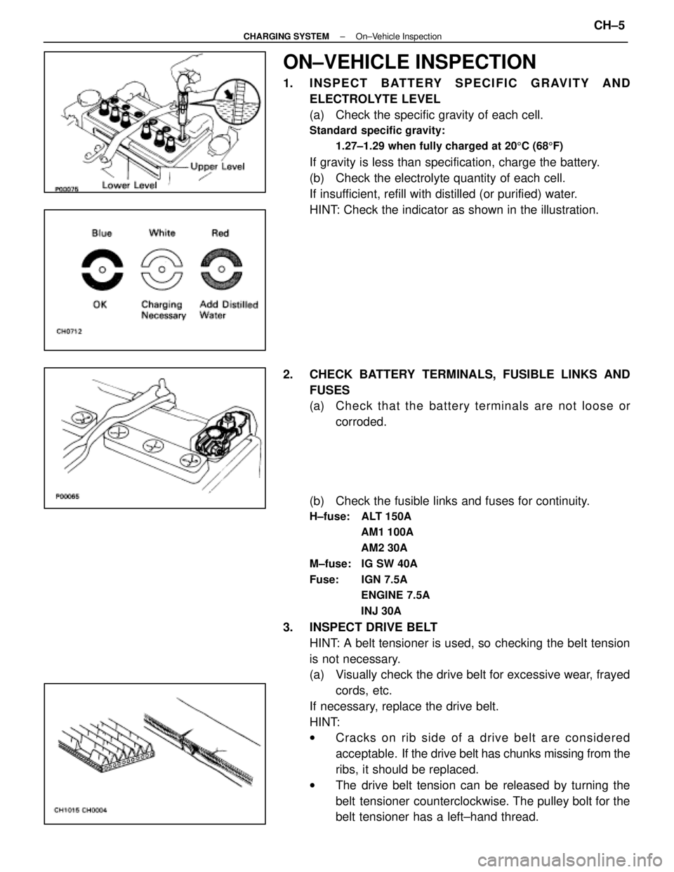
ON±VEHICLE INSPECTION
1. INSPECT BATTERY SPECIFIC GRAVITY ANDELECTROLYTE LEVEL
(a) Check the specific gravity of each cell.
Standard specific gravity:
1.27±1.29 when fully charged at 20 5C (68 5F)
If gravity is less than specification, charge the battery.
(b) Check the electrolyte quantity of each cell.
If insufficient, refill with distilled (or purified) water.
HINT: Check the indicator as shown in the illustration.
2. CHECK BATTERY TERMINALS, FUSIBLE LINKS AND FUSES
(a) Check that the battery terminals are not loose orcorroded.
(b) Check the fusible links and fuses for continuity.
H±fuse: ALT 150A AM1 100A
AM2 30A
M±fuse: IG SW 40A
Fuse: IGN 7.5A ENGINE 7.5A
INJ 30A
3. INSPECT DRIVE BELTHINT: A belt tensioner is used, so checking the belt tension
is not necessary.
(a) Visually check the drive belt for excessive wear, frayedcords, etc.
If necessary, replace the drive belt.
HINT:
w Cracks on rib side of a drive belt are considered
acceptable. If the drive belt has chunks missing from the
ribs, it should be replaced.
w The drive belt tension can be released by turning the
belt tensioner counterclockwise. The pulley bolt for the
belt tensioner has a left±hand thread.
±
CHARGING SYSTEM On±Vehicle InspectionCH±5
WhereEverybodyKnowsYourName
Page 1387 of 4087
wIf the vehicle has been running, wait 5 minutes or more
after the vehicle stops before measuring the battery
voltage.
If the voltage is less than specification, charge the battery.
HINT: Check the indicator as shown in the illustration.
1. C H E C K B AT T E RY S P E C I F I C G R AV I T Y A N D ELECTROLYTE LEVEL
2. CHECK BATTERY TERMINALS AND FUSES
(a) Check that the battery terminals are not loose or corroded.
(b) Check the fuses for continuity.
EG3F9±01
AIR FILTER INSPECTION AND
CLEANING
1. REMOVE AIR FILTER
(a) Open the air cleaner cap.
(b) Remove the air filter.
±
1UZ±FE ENGINE ENGINE MECHANICALEG±11
WhereEverybodyKnowsYourName
Page 2029 of 4087

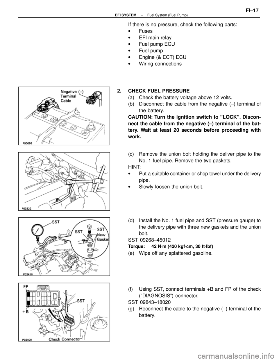
If there is no pressure, check the following parts:
wFuses
w EFI main relay
w Fuel pump ECU
w Fuel pump
w Engine (& ECT) ECU
w Wiring connections
2. CHECK FUEL PRESSURE (a) Check the battery voltage above 12 volts.
(b) Disconnect the cable from the negative (±) terminal ofthe battery.
CAUTION: Turn the ignition switch to ºLOCKº. Discon-
nect the cable from the negative (±) terminal of the bat-
tery. Wait at least 20 seconds before proceeding with
work.
(c) Remove the union bolt holding the deliver pipe to the No. 1 fuel pipe. Remove the two gaskets.
HINT:
w Put a suitable container or shop towel under the delivery
pipe.
w Slowly loosen the union bolt.
(d) Install the No. 1 fuel pipe and SST (pressure gauge) to the delivery pipe with three new gaskets and the union
bolt.
SST 09268±45012
Torque: 42 N Vm (420 kgf Vcm, 30 ft Vlbf)
(e) Wipe off any splattered gasoline.
(f) Using SST, connect terminals +B and FP of the check
(ºDIAGNOSISº) connector.
SST 09843±18020
(g) Reconnect the cable to the negative (±) terminal of the battery.
±
EFI SYSTEM Fuel System (Fuel Pump)FI±17
WhereEverybodyKnowsYourName
Page 2037 of 4087

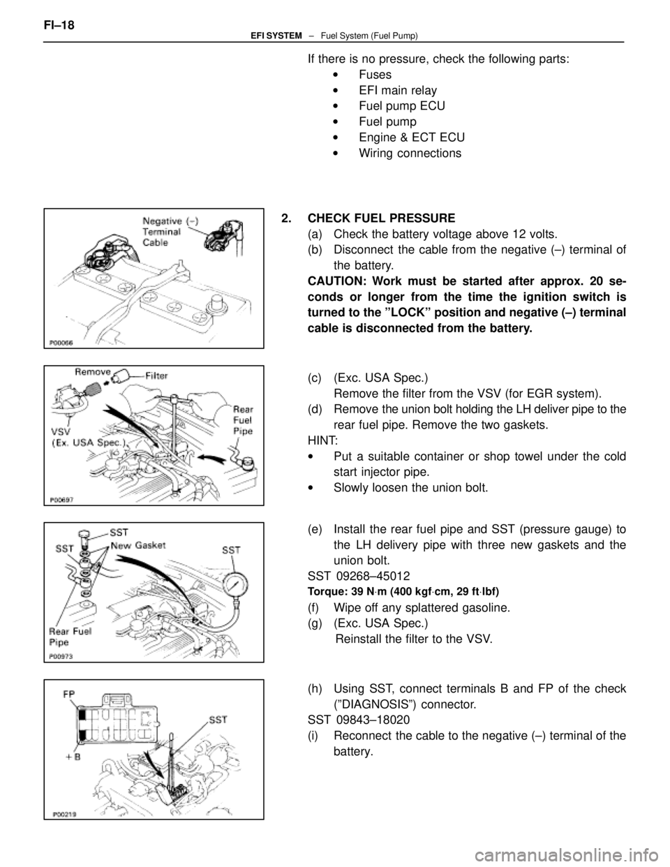
If there is no pressure, check the following parts:w Fuses
w EFI main relay
w Fuel pump ECU
w Fuel pump
w Engine & ECT ECU
w Wiring connections
2. CHECK FUEL PRESSURE (a) Check the battery voltage above 12 volts.
(b) Disconnect the cable from the negative (±) terminal ofthe battery.
CAUTION: Work must be started after approx. 20 se-
conds or longer from the time the ignition switch is
turned to the ºLOCKº position and negative (±) terminal
cable is disconnected from the battery.
(c) (Exc. USA Spec.) Remove the filter from the VSV (for EGR system).
(d) Remove the union bolt holding the LH deliver pipe to the
rear fuel pipe. Remove the two gaskets.
HINT:
w Put a suitable container or shop towel under the cold
start injector pipe.
w Slowly loosen the union bolt.
(e) Install the rear fuel pipe and SST (pressure gauge) to the LH delivery pipe with three new gaskets and the
union bolt.
SST 09268±45012
Torque: 39 N Vm (400 kgf Vcm, 29 ft Vlbf)
(f) Wipe off any splattered gasoline.
(g) (Exc. USA Spec.)
Reinstall the filter to the VSV.
(h) Using SST, connect terminals B and FP of the check (ºDIAGNOSISº) connector.
SST 09843±18020
(i) Reconnect the cable to the negative (±) terminal of the
battery.
FI±18
EFI SYSTEM
± Fuel System (Fuel Pump)
WhereEverybodyKnowsYourName