Page 3345 of 4087
DIAGNOSTIC CHART
DIAGNOSTIC
CHART
Check for short in all the harness and
components connected to IGN fuse.
Check voltage of terminal M±REL.
Check for open in harness and connector
between battery and ECU.
Check and replace ECU.
Replace ignition switch.
Repair or replace harness or
connector.
Repair or replace harness or
connector.
Check for open and short in harness and
connector between terminal M REL and body
ground.
Replace EFT main relay.
Check voltage of terminal IGSW.
Check IGN fuse.
Check continuity between terminals E1 and
body ground.
Check voltage of ECU power source.
Proceed to next circuit inspection
shown on matrix chart (See page
TR±35
).
Check ignition switch.
Check EFT fuse.
Check EFT main relay.
Check and repair or harness or connector
between EFI fuse and battery.
Check for short in all the harness and
components connected to EFI fuse.
±
ENGINE TROUBLESHOOTING Circuit InspectionTR±125
WhereEverybodyKnowsYourName
Page 3347 of 4087
OKNG
OKNG
4Check IGN Fuse.
C
OK
PRemove IGN fuse from J/B No.1.
Check continuity of IGN fuse.
Continuity.
Check for short in all the harness and components con-
nected to IGN fuse (See attached wiring diagram).
5Check ignition switch.
C
OK
PRemove under cover and finish panel.
Check continuity between terminals.
continuity
Replace ignition switch.
Check and repair harness and connector between
battery and ignition switch, ignition switch and en-
gine & ECT ECU.
±
ENGINE TROUBLESHOOTING Circuit InspectionTR±127
WhereEverybodyKnowsYourName
Page 3348 of 4087
OKNG
OKNG
6Check voltage between terminal M±REL of engine & ECT ECU connector and bod\
y ground.
C
OK
PTurn ignition switch on.
Measure voltage between terminal M±REL of engine &
ECT ECU connection and body ground.
Voltage: 10 ± 14 V
Check and replace engine & ECT ECU.
7Check EFI
C
OK
PRemove EFI fuse R/B No.2.
Check continuity of EFI fuse.
Continuity
Rep
TR±128
±
ENGINE TROUBLESHOOTING Circuit Inspection
WhereEverybodyKnowsYourName
Page 3349 of 4087
OKNG
OKNG
8Check EFI main relay.
C
OK
P
C
OK
Remove EFI main relay.
Check continuity between terminals of EFI main relay
shown below.
(2) Apply battery voltage between terminals 1 and 3.
(2) Check continuity between terminals 2 and 4.
Replace EFI main relay.
9Check for open and short in harness and connector between terminal M±REL o\
f engine & ECT
ECU and body ground (See page IN±27).
Repair or replace harness or connector.
Check and repair harness or connector between
EFI fuse and battery.
±
ENGINE TROUBLESHOOTING Circuit InspectionTR±129
WhereEverybodyKnowsYourName
Page 3350 of 4087
Check EFI fuse.
Check voltage of terminal BATT.
Check operation for the back±up.
Proceed to next circuit inspection
shown on matrix chart (See page TR±39).
Check for short in all the harness and
components connected to EFI fuse.
Check and repair harness or connector
between battery, EFI fuse and ECU.
Check and replace fuse.
WIRING DIAGRAM
Back Up Power Source Circuit
CIRCUIT DESCRIPTION
Battery voltage is supplied to terminal BATT of the ECU even when the ignition switch is off for use
by the diagnostic code memory and air±fuel ratio adaptive control val\
ue memory, etc.
DIAGNOSTIC CHART
TR±126±
ENGINE TROUBLESHOOTING Circuit Inspection
WhereEverybodyKnowsYourName
Page 3351 of 4087
OKNG
OKNG
YESNO
INSPECTION PROCEDURE
1Check EFI fuse.
C
OK
PRemove EFI fuse from R/B No. 2
Check continuity of EFI fuse.
Continuity
Check for short in all the harness and components
connected to EFI fuse (See attached wiring diagram).
2Check voltage between terminal BATT of engine (& ECT) ECU connector and body ground.
C
OK
PConnect the Check Harness A. (See page TR±34)
Measure voltage between terminal BATT of engine
(& ECT) ECU connector and body ground.
Voltage: 10 ± 14 V
Check and repair harness or connector between engine
(& ECT) ECU and EFI fuse, EFI fuse and battery.
3Are the diagnostic trouble codes still in the memory when the ignition s\
witch is turned OFF?
Check and replace engine (& ECT) ECU.
Proceed to next circuit inspection shown on
matrix chart (See page TR±39).
±
ENGINE TROUBLESHOOTING Circuit InspectionTR±127
WhereEverybodyKnowsYourName
Page 3352 of 4087
Injector Circuit
CIRCUIT DESCRIPTION
The injectors are provided to the intake manifold. They inject fuel into th\
e cylinders based on the
signals from the engine (& ECT) ECU.
Reference INSPECTION USING OSCILLOSCOPE
w With the engine idling measure between terminals #10 ~ 60 and E01 of engine (& ECT) ECU.
HINT: The correct waveform appears as shown in the illustration on the below\
.
DIAGNOSTIC CHART
Check voltage of terminals #10 ~ 60.
Check AM2 and INJ fuses.
Check for open in harness and connector
between ECU and battery.
Check continuity between terminals E01,
E02 and body ground.
Check operation for injectors.
Check and replace ECU. Check for short in all the harness
and components connected to
AM2 and INJ fuses.
Repair or replace harness or
connector.
Replace injector.
TR±128±
ENGINE TROUBLESHOOTING Circuit Inspection
WhereEverybodyKnowsYourName
Page 3354 of 4087
NGOK
OKNG
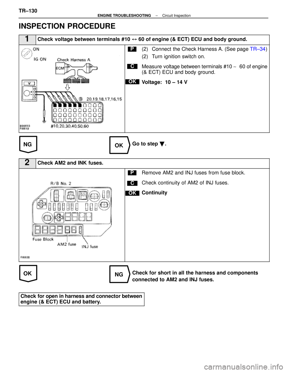
INSPECTION PROCEDURE
1Check voltage between terminals #10 � 60 of engine (& ECT) ECU and body ground.
C
OK
P(2) Connect the Check Harness A. (See page TR±34)
(2) Turn ignition switch on.
Measure voltage between terminals #10 ~� 60 of engine
(& ECT) ECU and body ground.
Voltage: 10 ± 14 V
Go to step �.
2Check AM2 and INK fuses.
C
OK
PRemove AM2 and INJ fuses from fuse block.
Check continuity of AM2 of INJ fuses.
Continuity
Check for short in all the harness and components
connected to AM2 and INJ fuses.
Check for open in harness and connector between
engine (& ECT) ECU and battery.
TR±130±
ENGINE TROUBLESHOOTING Circuit Inspection
WhereEverybodyKnowsYourName


 Apply battery voltage between terminals 1 and 3.
(2) Check co")
.
Check for short in all the harness and
co")

 ECU.
Reference INSPECTION")