Page 3669 of 4087

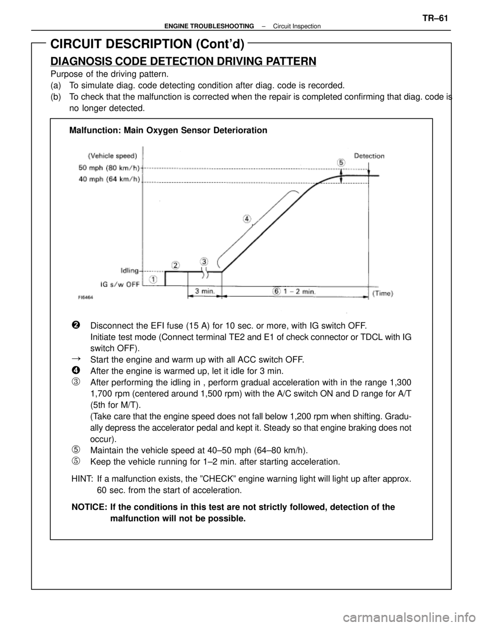
CIRCUIT DESCRIPTION (Cont'd)
DIAGNOSIS CODE DETECTION DRIVING PATTERN
Purpose of the driving pattern.
(a) To simulate diag. code detecting condition after diag. code is recorded.
(b) To check that the malfunction is corrected when the repair is completed co\
nfirming that diag. code isno longer detected.
�Disconnect the EFI fuse (15 A) for 10 sec. or more, with IG switch OFF\
.
Initiate test mode (Connect terminal TE2 and E1 of check connector or TDCL with IG
switch OFF).
�Start the engine and warm up with all ACC switch OFF.
�After the engine is warmed up, let it idle for 3 min.
�After performing the idling in , perform gradual acceleration with in th\
e range 1,300
1,700 rpm (centered around 1,500 rpm) with the A/C switch ON and D range fo\
r A/T
(5th for M/T).
(Take care that the engine speed does not fall below 1,200 rpm when shifting.\
Gradu-
ally depress the accelerator pedal and kept it. Steady so that engine br\
aking does not
occur).
�Maintain the vehicle speed at 40±50 mph (64±80 km/h).
�Keep the vehicle running for 1±2 min. after starting acceleration.
HINT: If a malfunction exists, the ºCHECKº engine warning light will light\
up after approx. 60 sec. from the start of acceleration.
NOTICE: If the conditions in this test are not strictly followed, detection of t\
he malfunction will not be possible.
Malfunction: Main Oxygen Sensor Deterioration
±
ENGINE TROUBLESHOOTING Circuit InspectionTR±61
WhereEverybodyKnowsYourName
Page 3687 of 4087

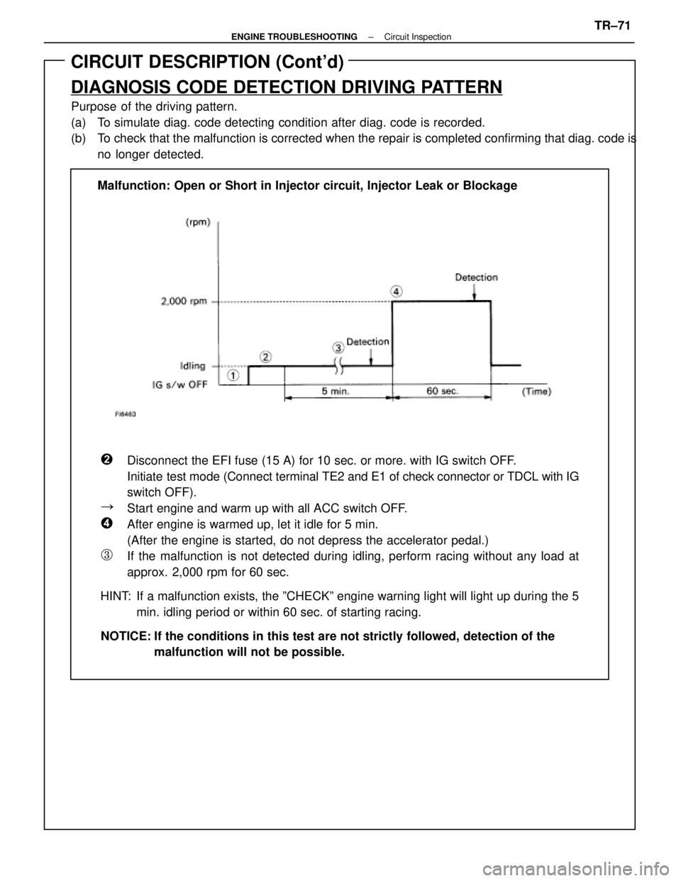
CIRCUIT DESCRIPTION (Cont'd)
DIAGNOSIS CODE DETECTION DRIVING PATTERN
Purpose of the driving pattern.
(a) To simulate diag. code detecting condition after diag. code is recorded.
(b) To check that the malfunction is corrected when the repair is completed co\
nfirming that diag. code isno longer detected.
�Disconnect the EFI fuse (15 A) for 10 sec. or more. with IG switch OFF\
.
Initiate test mode (Connect terminal TE2 and E1 of check connector or TDCL with IG
switch OFF).
�Start engine and warm up with all ACC switch OFF.
�After engine is warmed up, let it idle for 5 min.
(After the engine is started, do not depress the accelerator pedal.)
�If the malfunction is not detected during idling, perform racing without any load at
approx. 2,000 rpm for 60 sec.
HINT: If a malfunction exists, the ºCHECKº engine warning light will light\
up during the 5 min. idling period or within 60 sec. of starting racing.
NOTICE: If the conditions in this test are not strictly followed, detection of t\
he malfunction will not be possible.
Malfunction: Open or Short in Injector circuit, Injector Leak or Blockag\
e
±
ENGINE TROUBLESHOOTING Circuit InspectionTR±71
WhereEverybodyKnowsYourName
Page 3703 of 4087

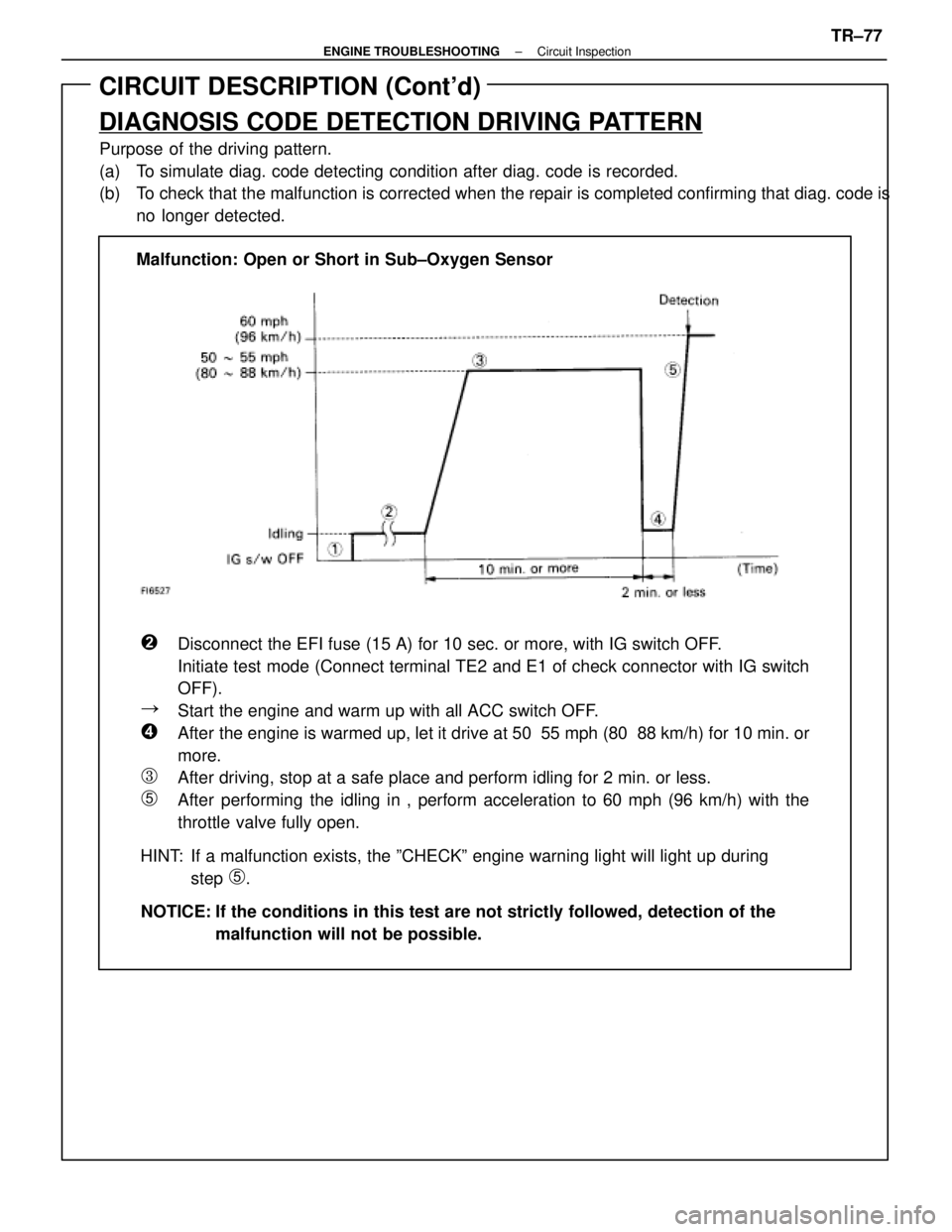
CIRCUIT DESCRIPTION (Cont'd)
DIAGNOSIS CODE DETECTION DRIVING PATTERN
Purpose of the driving pattern.
(a) To simulate diag. code detecting condition after diag. code is recorded.
(b) To check that the malfunction is corrected when the repair is completed co\
nfirming that diag. code isno longer detected.
�Disconnect the EFI fuse (15 A) for 10 sec. or more, with IG switch OFF\
.
Initiate test mode (Connect terminal TE2 and E1 of check connector with\
IG switch
OFF).
�Start the engine and warm up with all ACC switch OFF.
�After the engine is warmed up, let it drive at 50 55 mph (80 88 km/h) for\
10 min. or
more.
�After driving, stop at a safe place and perform idling for 2 min. or les\
s.
�After performing the idling in , perform acceleration to 60 mph (96 km/h) with the
throttle valve fully open.
HINT: If a malfunction exists, the ºCHECKº engine warning light will lig\
ht up during step
�.
NOTICE: If the conditions in this test are not strictly followed, detection of t\
he malfunction will not be possible.
Malfunction: Open or Short in Sub±Oxygen Sensor
±
ENGINE TROUBLESHOOTING Circuit InspectionTR±77
WhereEverybodyKnowsYourName
Page 3737 of 4087

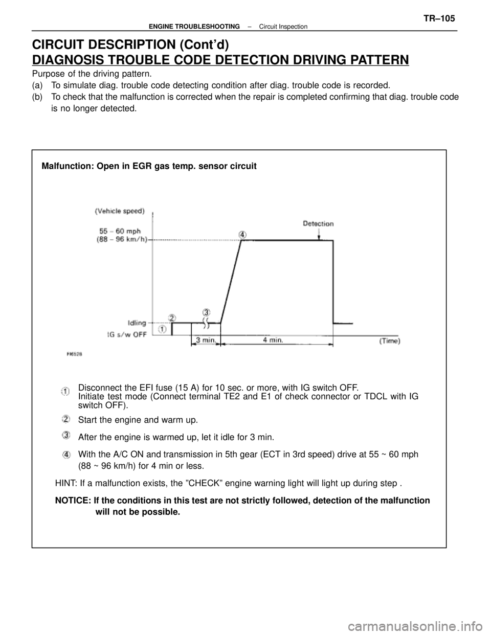
CIRCUIT DESCRIPTION (Cont'd)
DIAGNOSIS TROUBLE CODE DETECTION DRIVING PATTERN
Purpose of the driving pattern.
(a) To simulate diag. trouble code detecting condition after diag. trouble co\
de is recorded.
(b) To check that the malfunction is corrected when the repair is completed co\
nfirming that diag. trouble codeis no longer detected.
Malfunction: Open in EGR gas temp. sensor circuit
Disconnect the EFI fuse (15 A) for 10 sec. or more, with IG switch OFF\
.
Initiate test mode (Connect terminal TE2 and E1 of check connector or TDCL with\
IG
switch OFF).
Start the engine and warm up.
After the engine is warmed up, let it idle for 3 min.
With the A/C ON and transmission in 5th gear (ECT in 3rd speed) drive at 5\
5 ~ 60 mph
(88 ~ 96 km/h) for 4 min or less.
HINT: If a malfunction exists, the ºCHECKº engine warning light will l\
ight up during step .
NOTICE: If the conditions in this test are not strictly followed, detection of \
the malfunction will not be possible.
±
ENGINE TROUBLESHOOTING Circuit InspectionTR±105
WhereEverybodyKnowsYourName
Page 3761 of 4087
Check voltage of ECU power source.
Check continuity between terminals E1 and
body ground.
Check voltage of terminal IGSW.
Check IGN fuse.
Check ignition switch.
Check for open in harness and connector
between battery and ECU.
Check voltage of terminal M±REL.
Check EFI fuse.
Check EFI main relay.Check for open and short in harness and
connector between terminal M±REL and
body ground.
Check and repair harness or connector
between EFI fuse and battery.
Repair or replace harness or
connector.
Replace EFI main relay.
Check for short in all the harness
and components connected to the
EFI fuse.
Check and replace ECU.
Replace ignition switch.
Check for short in all the harness and
components connected to IGN fuse.
Repair or replace harness or
connector.
Proceed to next circuit inspection
shown on matrix cart (See page
TR±39
).
DIAGNOSTIC CHART
±
ENGINE TROUBLESHOOTING Circuit InspectionTR±121
WhereEverybodyKnowsYourName
Page 3763 of 4087
OKNG
OKNG
4Check IGN fuse.
C
OK
PRemove IGN fuse from J/B No. 1.
Check continuity of IGN fuse.
Continuity
Check for short in all the harness and components con-
nected to IGN fuse (See attached wiring diagram).
5Check ignition switch.
C
OK
PRemove under cover and finish panel.
Check continuity between terminals.
Replace ignition switch.
Check and repair harness and connector between
battery and ignition switch, ignition switch and en-
gine (& ECT) ECU.
±
ENGINE TROUBLESHOOTING Circuit InspectionTR±123
WhereEverybodyKnowsYourName
Page 3764 of 4087
OKNG
OKNG
6Check voltage between terminal M±REL of engine (& ECT) ECU connector and\
body ground.
C
OK
PTurn ignition switch on.
Measure voltage between terminal M±REL of engine
(& ECT) ECU connector and body ground.
Voltage: 10 ± 14 V
Check and replace engine (& ECT) ECU.
7Check EFI fuse.
C
OK
PRemove EFI fuse from R/B No. 2.
Check continuity of EFI fuse.
Continuity
Check for short in all the harness and components
connected to EFI fuse (See attached wiring diagram).
TR±124
±
ENGINE TROUBLESHOOTING Circuit Inspection
WhereEverybodyKnowsYourName
Page 3765 of 4087
OKNG
OKNG
8Check EFI main relay.
C
OK
P
OK
C
Remove EFI main relay.
Check continuity between terminals of EFI main relay
shown below.
1. Apply battery positive voltage between terminals 1and 3.
2. Check continuity between terminals 2 and 4.
Replace EFI main relay.
9Check for open and short in harness and connector between terminal M±REL of\
engine (& ECT)
ECU and body ground (See page IN±27).
Repair or replace harness or connector.
Check and repair harness or connector between
EFI fuse and battery.
±
ENGINE TROUBLESHOOTING Circuit InspectionTR±125
WhereEverybodyKnowsYourName